Receiver which demodulates OFDM symbol

a demodulation and received signal technology, applied in the field of receiving signals, can solve the problems of reducing the effect of selective frequency fading, affecting the quality of the received signal, so as to reduce the interference of inter-symbols

Inactive Publication Date: 2007-12-25
FUJITSU LTD
View PDF3 Cites 33 Cited by
  • Summary
  • Abstract
  • Description
  • Claims
  • Application Information

AI Technical Summary

Benefits of technology

[0017]The receiver which demodulates the OFDM symbol transmitted by the OFDM method as described above enables the provision of a receiver which reduces the inter-symbol interference which is caused by the delayed wave which arrives with a delay exceeding the guard interval in the OFDM symbol. Furthermore, the provision of a receiver which has a small-sized demodulation circuit and the maintenance of the soft-decision information at the time of the demodulation are enabled.
[0019]The receiver which demodulates the OFDM symbol transmitted by the OFDM method as described above enables the provision of a receiver which reduces the inter-symbol interference which is caused by the delayed wave which arrives with a delay exceeding the guard interval in the OFDM symbol. Furthermore, the provision of a receiver which has a small-sized demodulation circuit and performs the maintenance of the soft-decision information at the time of the demodulation is enabled.

Problems solved by technology

The multi-carrier modulation method suppresses an effect of selective frequency fading, which becomes particularly problematic in the multi-path propagation environment, by using a plurality of carriers (or sub-carriers) in a predetermined transmission band so as to transmit signals in parallel.
On the other hand, the delay spread differs greatly from one communications environment to another.
Therefore, the method is disadvantageous from such points of view as circuit size, computational complexity, and power consumption of the receiver.
It is particularly disadvantageous for use in a mobile communications device which needs to be kept small.
As the provision of a receiver circuit which is adapted to the largest modulation index M is needed when the related-art technology is used in the communications system, the related-art method is also disadvantageous from the point of view that embedding in the adaptive modulation system is difficult.
Furthermore, the related-art method is also disadvantageous as a hard decision of a demodulated signal is made by performing the MLSE so that, likelihood information for the soft-decision information, is lost and the error correction technology cannot be utilized 100%.

Method used


Image

  • Receiver which demodulates OFDM symbol
  • Receiver which demodulates OFDM symbol
  • Receiver which demodulates OFDM symbol

Examples


first embodiment

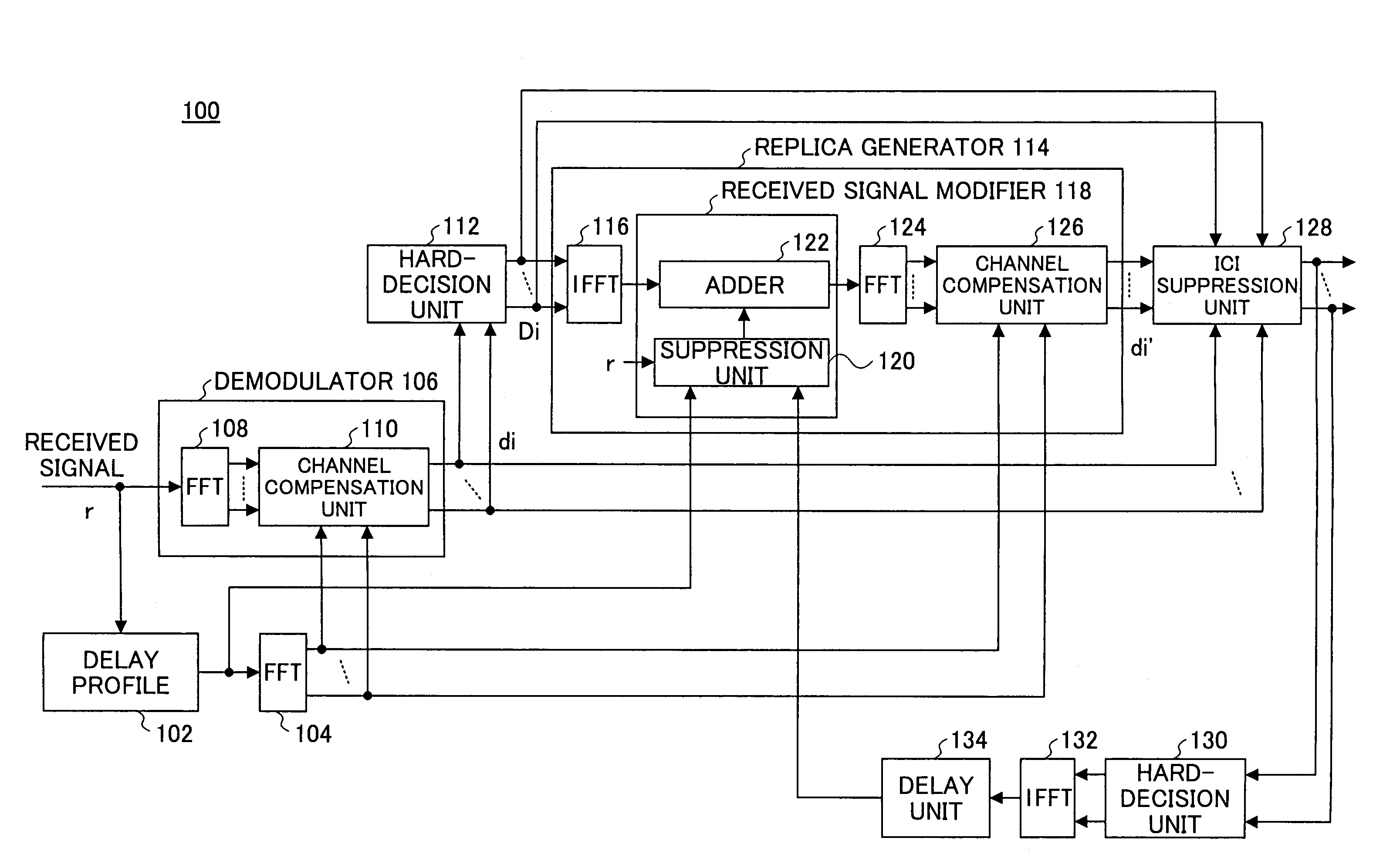
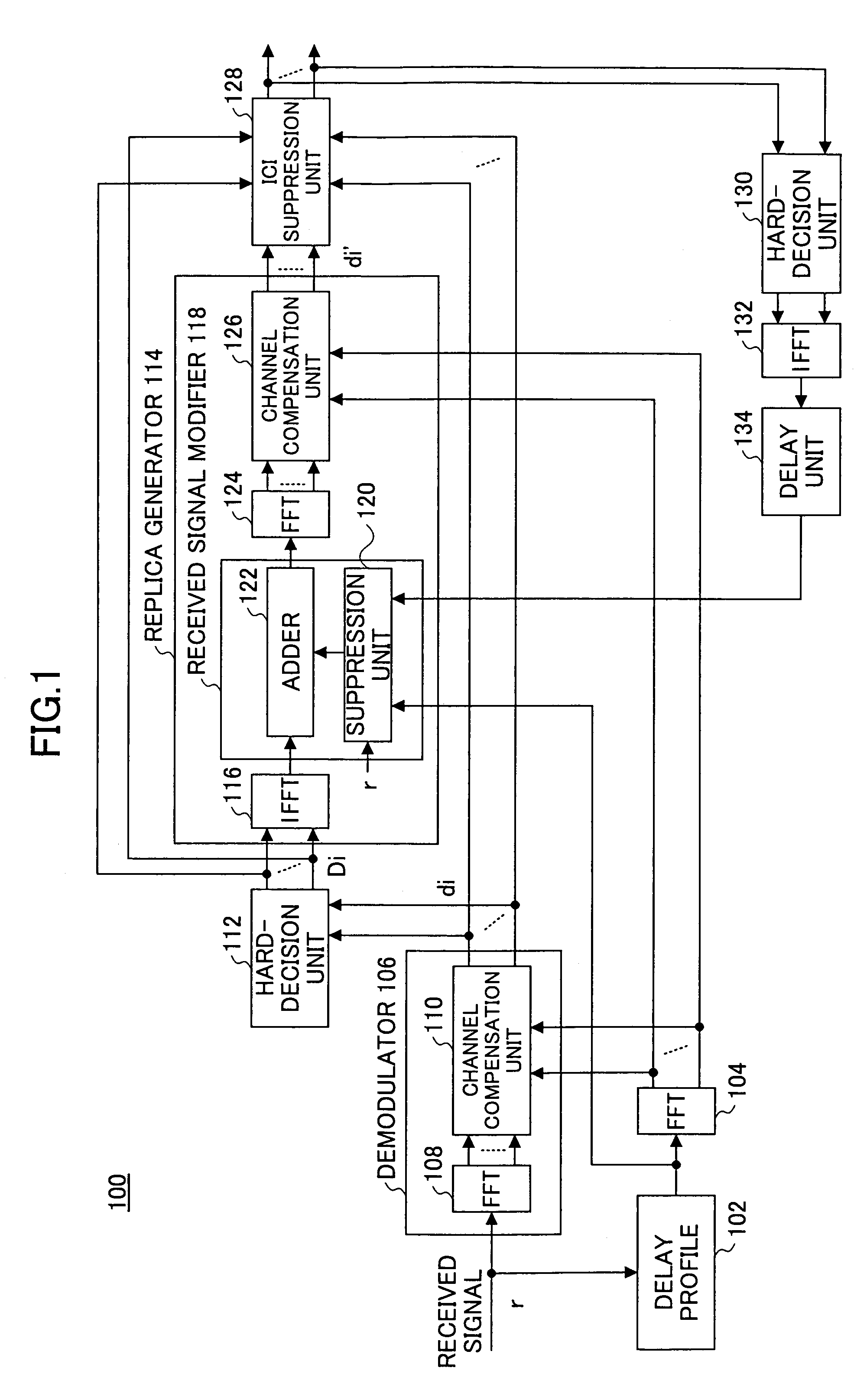
[0029]FIG. 1 is a functional block diagram of a receiver according to the present invention. The receiver 100 comprises a delay profile generator 102 which receives a signal which is transmitted by the OFDM method so as to generate a delay profile regarding the received signal. The output of the delay profile generator 102 is provided to the FFT 104 which performs FFT on the input signal. Besides, for brevity, the portions which perform the serial-to-parallel conversion and the parallel-to-serial conversion related to the FFT process and the below IFFT (Inverse FFT) process are omitted. The receiver 100 comprises a demodulator 106, the demodulator 106 comprising a FFT 108 which performs FFT on the received signal and a channel compensation unit 110 which is connected to the FFT 108. The channel compensation unit 110 based on the information from the delay profile 102 which is obtained via the FFT 104 adjusts per sub-carrier the amplitude and the phase of the signal from the FFT 108 ...

second embodiment

[0042]FIG. 3 illustrates a functional block diagram of a receiver according to the present invention. The receiver 300 comprises the delay profile generator 302 which receives the OFDM signal so as to generate the delay profile. The delay profile generator 302 is connected to the FFT 304 which performs FFT. Besides, for brevity, the portions which perform the serial-parallel conversion and / or the parallel-to-serial conversion related to FFT or IFFT are omitted. The receiver 300 comprises the demodulator 306, the demodulator 306 comprising the FFT 308 which performs FFT and the channel compensation unit 310 which is connected to the FFT 308. The channel compensation unit 310 adjusts the amplitude and the phase of the output signals of the FFT 308 based on the delay profile so as to output the demodulated signal per sub-carrier.

[0043]The receiver 300 comprises the hard-decision unit 312 which is connected to the demodulator 306, the hard-decision unit 312 making the hard decision per ...

third embodiment

[0058]FIG. 6 is a functional block diagram of a receiver according to the present invention. The receiver 600 comprises the delay profile generator 602 which generates the delay profile of the OFDM signal with the guard interval removed. The output of the delay profile generator 602 is provided to the FFT 604 which performs the FFT. The receiver 600 comprises the demodulator 606, the demodulator 606 performing FFT on the received signal and channel compensation using the delay profile so as to output a first demodulated signal A.

[0059]The receiver 600 comprises a first demodulated signal modifier 603, the first demodulated signal modifier 603 outputting a second demodulated signal B which modifies the first demodulated signal A. The receiver 600 comprises a second demodulated signal modifier 605, the second demodulated signal modifier 605 outputting a third demodulated signal C which modifies the second demodulated signal B. Furthermore, the receiver 600 comprises a third demodulate...


PUM


Abstract

A receiver is disclosed that demodulates an Orthogonal Frequency Division Multiplexing (OFDM) symbol transmitted by an OFDM method. The receiver includes a delay profile generation unit that generates a delay profile regarding a preceding wave and a delayed wave included in a received signal, a demodulation unit that demodulates the received signal so as to output a demodulated signal per sub-carrier, a hard-decision unit that makes a hard decision per sub-carrier on a signal point based on the demodulated signal so as to output a hard-decision signal, a replica generation unit that uses the hard-decision signal to generate a replica signal per sub-carrier, and an inter-carrier interference suppression unit that adds a difference between the hard-decision signal and the replica signal to the demodulated signal so as to suppress an inter-carrier interference.

Description

BACKGROUND OF THE INVENTION[0001]1. Field of the Invention[0002]The present invention generally relates to a technology for demodulating a received signal, and particularly relates to a receiver for demodulating a signal which is transmitted by the Orthogonal Frequency Division Multiplexing (OFDM) method (or an OFDM signal or symbol).[0003]2. Description of the Related Art[0004]In wideband wireless communications, or the next-generation mobile communications currently being studied within the technical field, a system which provides for a multi-path propagation environment needs to be built. The multi-carrier modulation method suppresses an effect of selective frequency fading, which becomes particularly problematic in the multi-path propagation environment, by using a plurality of carriers (or sub-carriers) in a predetermined transmission band so as to transmit signals in parallel. The OFDM method in particular adds a Guard Interval (GI) between symbols which are effective. Hereby,...

Claims


Application Information

Patent Timeline
Patent Type & Authority Patents(United States)
IPC IPC(8): H04L27/28H04J11/00H04L25/03H04L27/26
CPCH04L27/2647H04L2025/03414
Inventor YOSHIDA, MAKOTOISHIZU, EIZOU
Owner FUJITSU LTD
Why Eureka
Try Eureka