
Decoder for pin-based scan test

a pin-based scan and decoder technology, applied in the direction of electronic circuit testing, measurement devices, instruments, etc., can solve the problems of cumbersome application of such instructions, debugging setup effort, and general undesirable shifts of instructions, so as to avoid degrading application performance

Active Publication Date: 2007-12-25
ORACLE INT CORP
View PDF2 Cites 7 Cited by
  • Summary
  • Abstract
  • Description
  • Claims
  • Application Information

AI Technical Summary

Benefits of technology

[0008]Broadly speaking, the present invention fills these needs by providing a simple combinational configuration mechanism for entering manufacturing test which avoids degrading application performance by functionally overloading pre-existing, non-critical test ports. It should be appreciated that the present invention can be implemented in numerous ways, including as a process, an apparatus, a system, a device, or a method. Several inventive embodiments of the present invention are described below.

Problems solved by technology

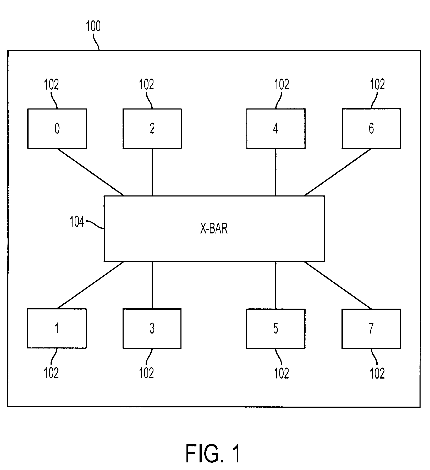
Typically, a pin-based access is generally utilized for testing, but as circuitry becomes more complex, functional modes require use and control of most available existing device pins.
However, the shifting in of instructions is generally undesirable as a method of configuring the device for production test since it involves the use of sequential elements before they have been screened for manufacturing defects.
Further, application of such instructions can be cumbersome and can complicate efforts to debug the setup in the event that the initialization sequence malfunctions.
Moreover, such a modification would add unnecessary loading to the functional path, with a corresponding degradation in performance.

Method used


Image

  • Decoder for pin-based scan test
  • Decoder for pin-based scan test
  • Decoder for pin-based scan test

Examples


Embodiment Construction

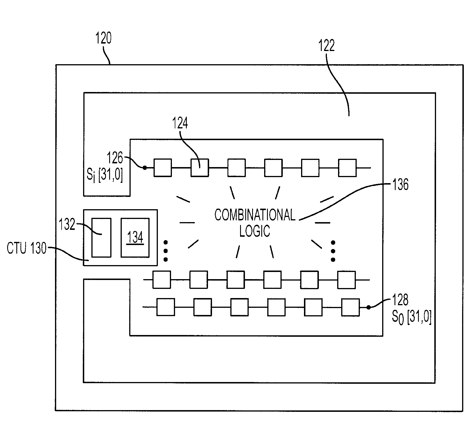
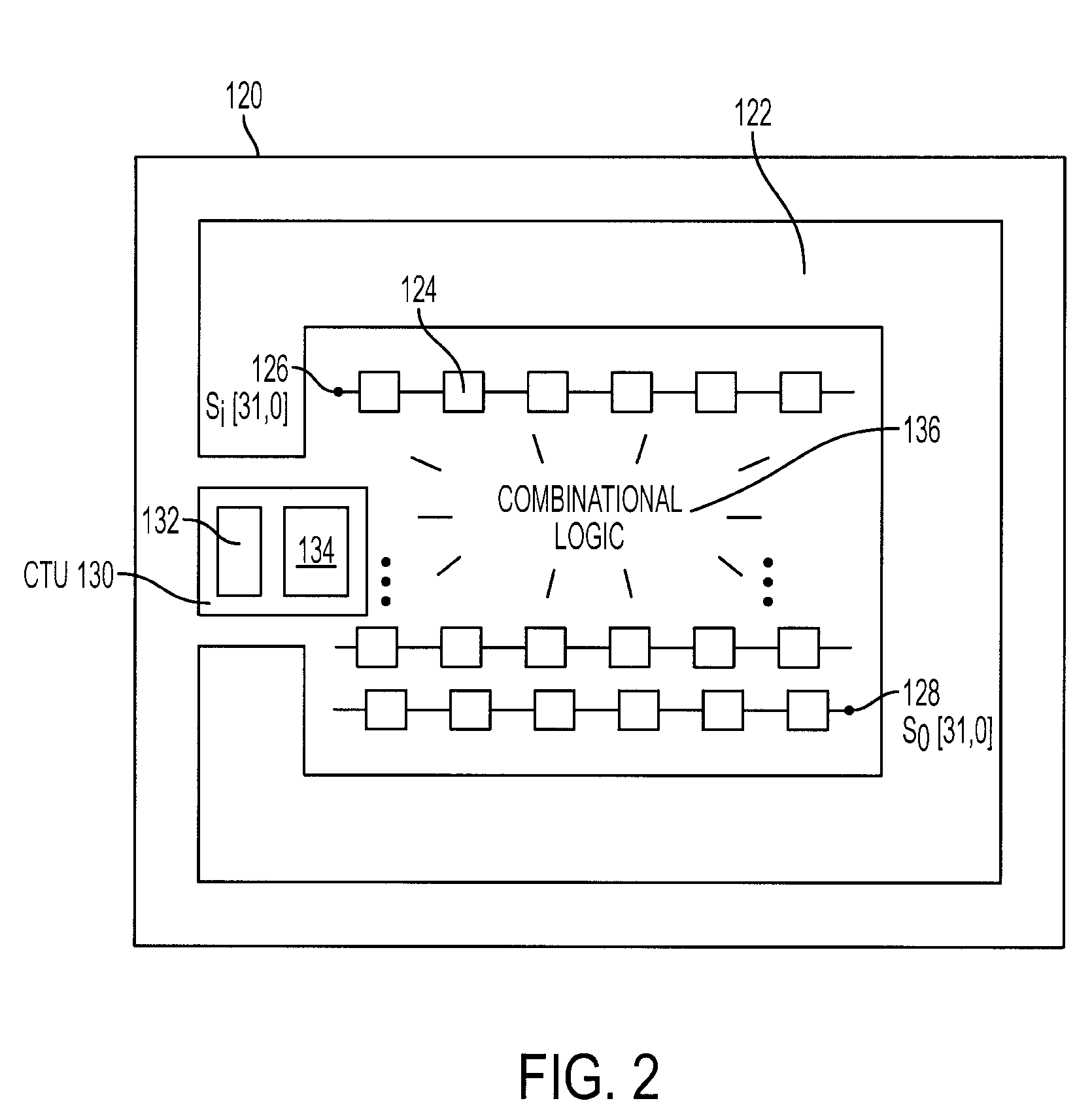
[0019]An invention for a circuit design block providing pin-based access to full-scan production testing while maintaining full compliance with 5-pin IEEE 1149.1 at the system level, and full compliance with 4-pin IEEE 1149.1 for applicable production modes is described. In exemplary embodiments, pin-based access is obtained through the Test Access Port or TAP, while maintaining the desired IEEE compliance.

[0020]In the following description, numerous specific details are set forth in order to provide a thorough understanding of the present invention. It will be understood, however, to one skilled in the art, that the present invention may be practiced without some or all of these specific details. In other instances, well known process operations have not been described in detail in order not to unnecessarily obscure the present invention.

[0021]Embodiments of the present invention provide for pin-based access for full-scan production testing of increasingly complex circuitry. Device...


PUM


Abstract

An integrated circuit design block includes combinational and sequential logic defining core logic of the integrated circuit design block, and boundary logic defined at an outer region of the integrated circuit design block. The integrated circuit design block also includes a control test unit that has a scan chain decoder and a boundary scan decoder. The scan chain decoder includes scan chain select circuitry for enabling the scan chain decoder during scan testing of the core logic. The scan chain select circuitry further includes a pin for disabling the scan chain decoder during testing of the boundary logic. The scan chain decoder is limited to share pins defined by the boundary scan decoder, and is both 4-pin and 5-pin IEEE 1149.1 compliant.

Description

BACKGROUND OF THE INVENTION[0001]1. Field of the Invention[0002]The present invention relates generally to integrated circuit design and testing, and more specifically to pin-based access for full-scan production testing of an integrated circuit device.[0003]2. Description of the Related Art[0004]In the testing of integrated circuits and circuit devices, an access mechanism is desired to configure the device for full-scan production test. Typically, a pin-based access is generally utilized for testing, but as circuitry becomes more complex, functional modes require use and control of most available existing device pins. What is desired is a pin-based access without increasing the pin count which would fundamentally alter the cell type.[0005]In one prior art approach, scan test access is available by shifting in pre-defined instructions. However, the shifting in of instructions is generally undesirable as a method of configuring the device for production test since it involves the us...

Claims


Application Information

Patent Timeline
Patent Type & Authority Patents(United States)
IPC IPC(8): G01R31/28
CPCG01R31/31719G01R31/318572G01R31/318547
Inventor MISTELY, ROGER C.
Owner ORACLE INT CORP
Learn More