Multi-position locking mechanisms for clamping assemblies

Inactive Publication Date: 2008-01-01
KOROS TIBOR +1
View PDF12 Cites 84 Cited by
  • Summary
  • Abstract
  • Description
  • Claims
  • Application Information

AI Technical Summary

Benefits of technology

[0008]The present invention provides a multi-position locking mechanism which can be used with a clamping device(s) to create and maintain the necessary actuating or clamping force to maintain the device in a clamped position without substantial risk of slippage. The present invention is practical and particularly useful in the medical field as part of a surgical retraction apparatus used to p

Problems solved by technology

While a camming member is useful in producing the actuating force needed to move the various clamping devices in the clamped position, there is always a possibility that the camming surface can “slip” once placed in the clamped position which can diminish the force acting on the respective clamping devices.
It should be appreciated that such a reduction in this clamping force is undesirable since the tension applied by the retractor blade to the retracted tis

Method used


Image

  • Multi-position locking mechanisms for clamping assemblies
  • Multi-position locking mechanisms for clamping assemblies
  • Multi-position locking mechanisms for clamping assemblies

Examples


Embodiment Construction

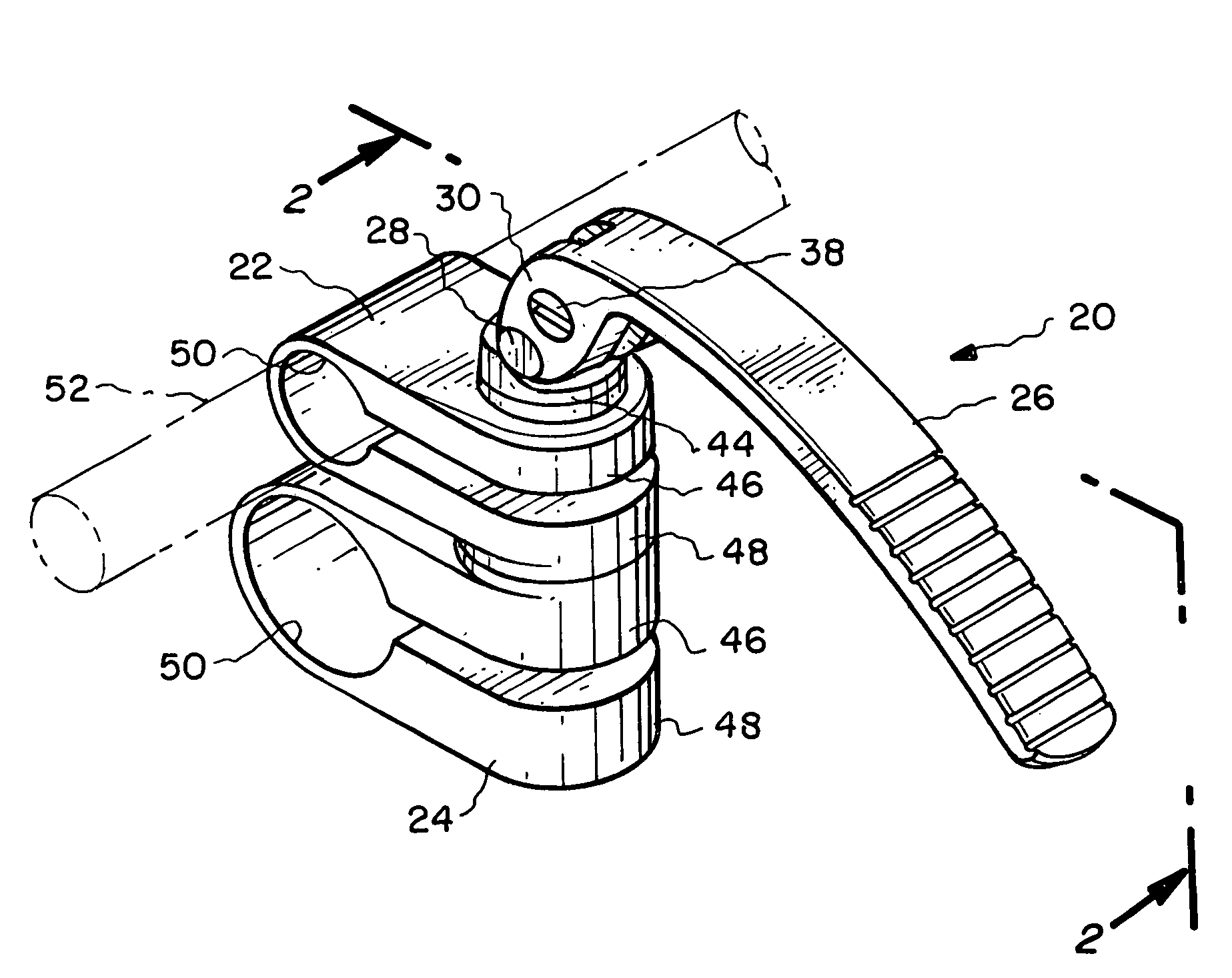
[0033]In one aspect, the present invention relates to locking mechanisms which can be used to deliver an actuating force that moves and locks, for example, a clamping device(s) between its clamped and unclamped positions. For the sake of illustration, the following exemplary embodiments of the invention are directed to clamping devices used in a surgical retraction system, although it should be understood that the present invention is applicable to other medical device applications, as well as non-medical applications.

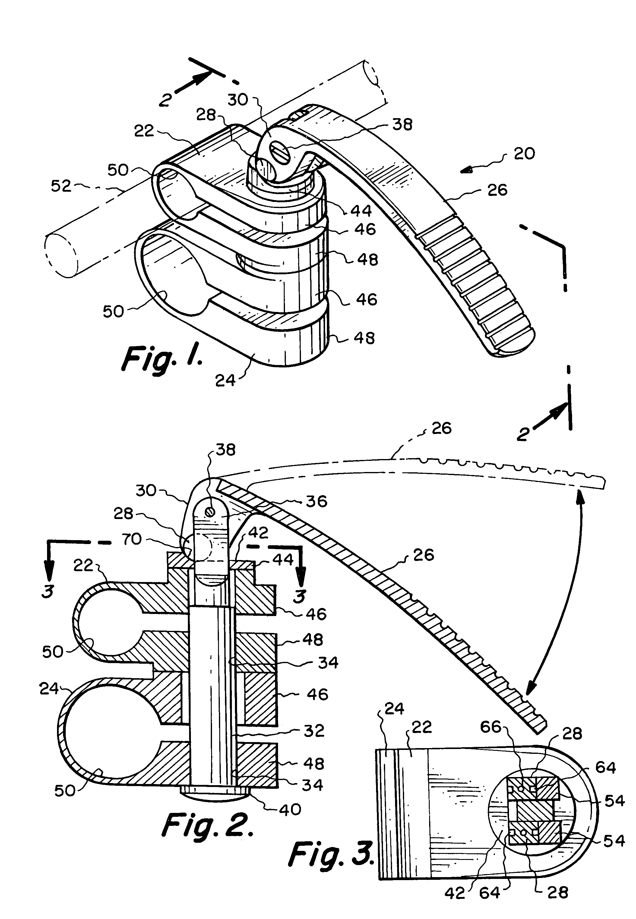
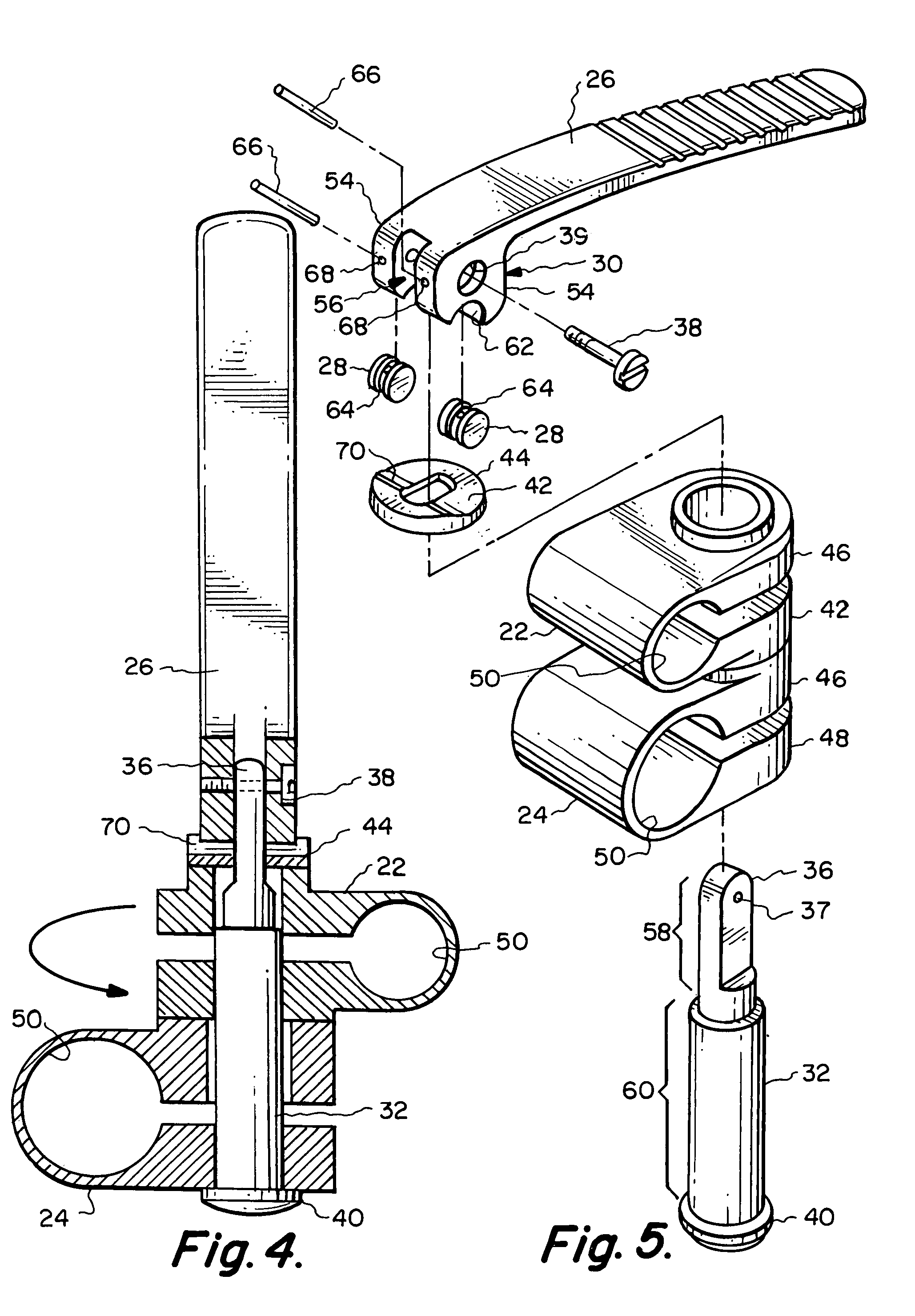
[0034]Referring now to FIGS. 1-5, one particular embodiment of a multi-position locking mechanism 20 is shown. The locking mechanism 20 is used to impart an actuating or compressive force on a first clamping member 22 and a second clamping member 24 which are coupled to the locking mechanism 20. The combination of the locking mechanism 20 and the first clamping member 22 and second clamping member 24 creates a composite retractor clamp which is capable of being utilize...


PUM


Abstract

A locking mechanism for a clamping assembly includes a roller locking mechanism, at least one clamping member and a shaft member for coupling the roller locking mechanism with the first clamping member. The roller mechanism includes a roller rotatably connected to a handle which contacts a bearing surface to place a compressive force on the first clamping member when the handle is actuated. Another locking mechanism includes a camming member having cam face with a sliding cam surface and a frictional cam surface adjacent to the sliding cam surface. The camming member produces a compressive force on the clamping member as the sliding cam surface contacts a bearing surface and increased static friction when the frictional cam surface contacts the bearing surface to help maintain the camming member in a locked position. Another locking mechanism includes a support frame, a camming member pivotally attached to the support frame, a clamping member and a shaft member for coupling the roller locking mechanism with the first clamping member, the shaft member including a sliding pin which remains in sliding engagement with the camming member.

Description

BACKGROUND OF THE INVENTION[0001]The present invention generally relates to clamping devices for connecting discrete elements together, and more particularly, to locking mechanisms which can be used with clamping devices to provide the actuating force needed to move and maintain the clamping devices in a clamped and unclamped position. The present invention also is directed to locking mechanisms which can be associated with camming devices to increase the frictional contact between the cam surface and the contact surface to increase the ability of the camming member to be “locked” in a set position. While the present invention is described with particularity in use within the medical field, particularly to clamping devices used with surgical retraction systems, it should be appreciated that the present invention could be used in non-medical applications where the quick release of clamped elements is desired.[0002]Various surgical retraction systems have been developed over the years...

Claims


Application Information

Patent Timeline
IPC IPC(8): B25G3/36
CPCA61B19/26A61B17/02Y10T403/7171Y10S403/04Y10T403/7105A61B2019/267A61B90/57A61B90/50
Inventor KOROS, TIBORKOROS, GABRIEL
Owner KOROS TIBOR
Why Eureka
Try Eureka