
Power supply for switching operation, electronic apparatus including the same, and method of controlling the same

a technology of power supply and operation, applied in the direction of automatic control, process and machine control, instruments, etc., can solve the problems of inkjet printers, ink discharge performance varies, problem becomes serious, etc., and achieve the effect of suppressing the data amount of the control table and high speed without reducing the power supply efficiency

Inactive Publication Date: 2008-01-01
CANON KK
View PDF7 Cites 10 Cited by
  • Summary
  • Abstract
  • Description
  • Claims
  • Application Information

AI Technical Summary

Benefits of technology

The present invention is a power supply for switching operation that can change the output voltage quickly without decreasing the efficiency of the power supply. It uses a switching circuit and an output circuit to generate a pulse output. A control table stores data on the ON and OFF periods of the switching circuit in correspondence with a set voltage. An arithmetic processing unit performs reading and PWM operations based on the control table. A digital control unit controls the switching circuit by outputting a PWM signal. The power supply can change the output voltage by either feedback control or data read from the control table. The invention allows for high-speed switching without decreasing the power supply efficiency and reduces the data amount of the control table. It is particularly useful in electronic apparatuses such as printing apparatuses.

Problems solved by technology

If the load on the power supply increases, the ink discharge performance varies due to a driving voltage drop.
This problem becomes serious particularly when the number of concurrently driven nozzles changes in accordance with print data.
This problem occurs not only in the inkjet printer but also in a printing apparatus which adopts another printing method using many printing elements.
The temperature rise of the nozzle changes ink bubbling, changes the ink discharge amount and discharge position precision, and causes quality deterioration.
However, in the method described in Japanese Patent Publication Laid Open No. 2001-225457 if many driving voltage sources of different voltages are used, this causes to increase the circuit scale and cost.
It is, therefore, difficult to finely regulate (set) the driving voltage in consideration of the circuit scale and cost.
Increasing the switching frequency increases power loss in the power supply and generates a large amount of heat in the power supply.

Method used


Image

  • Power supply for switching operation, electronic apparatus including the same, and method of controlling the same
  • Power supply for switching operation, electronic apparatus including the same, and method of controlling the same
  • Power supply for switching operation, electronic apparatus including the same, and method of controlling the same

Examples


first embodiment

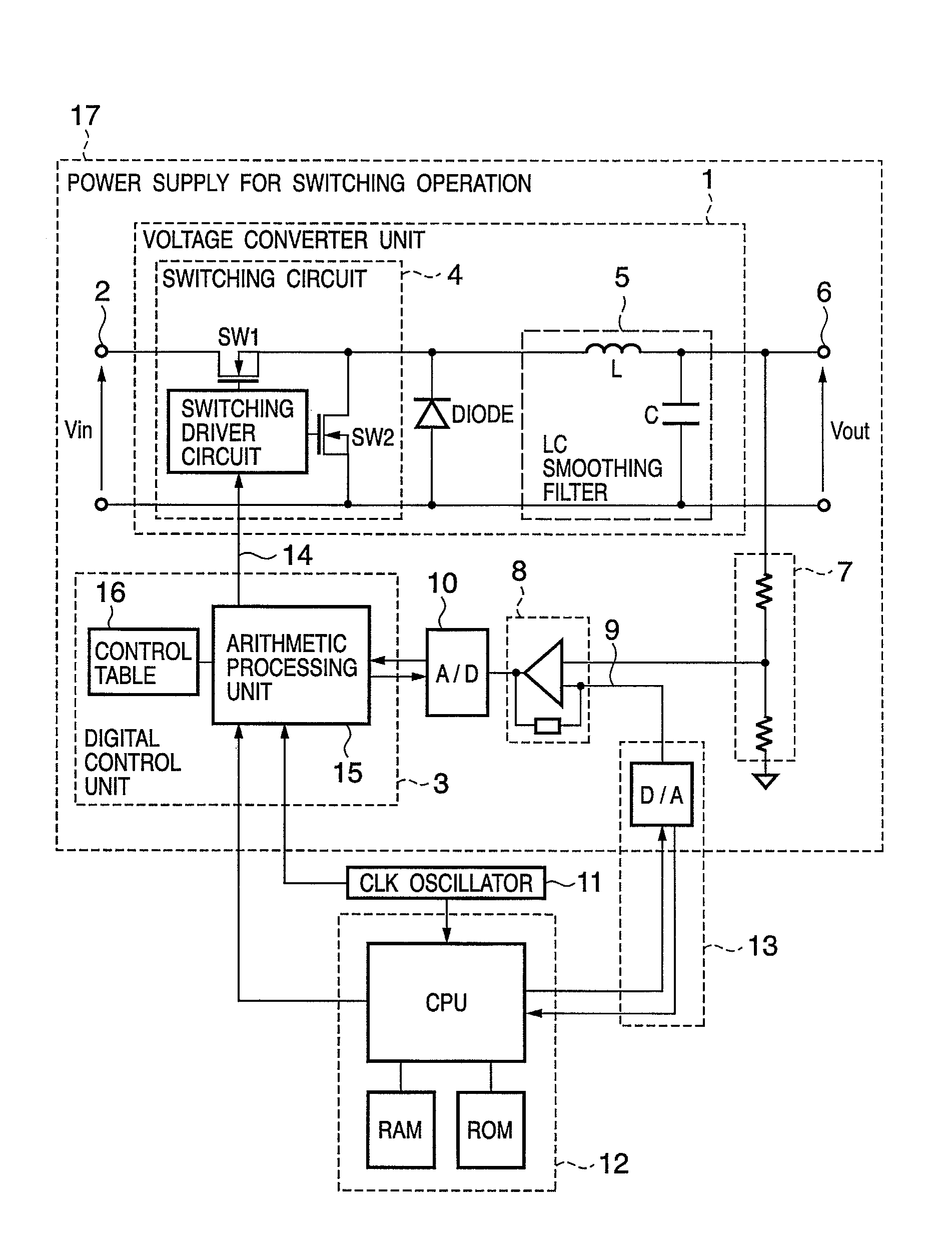
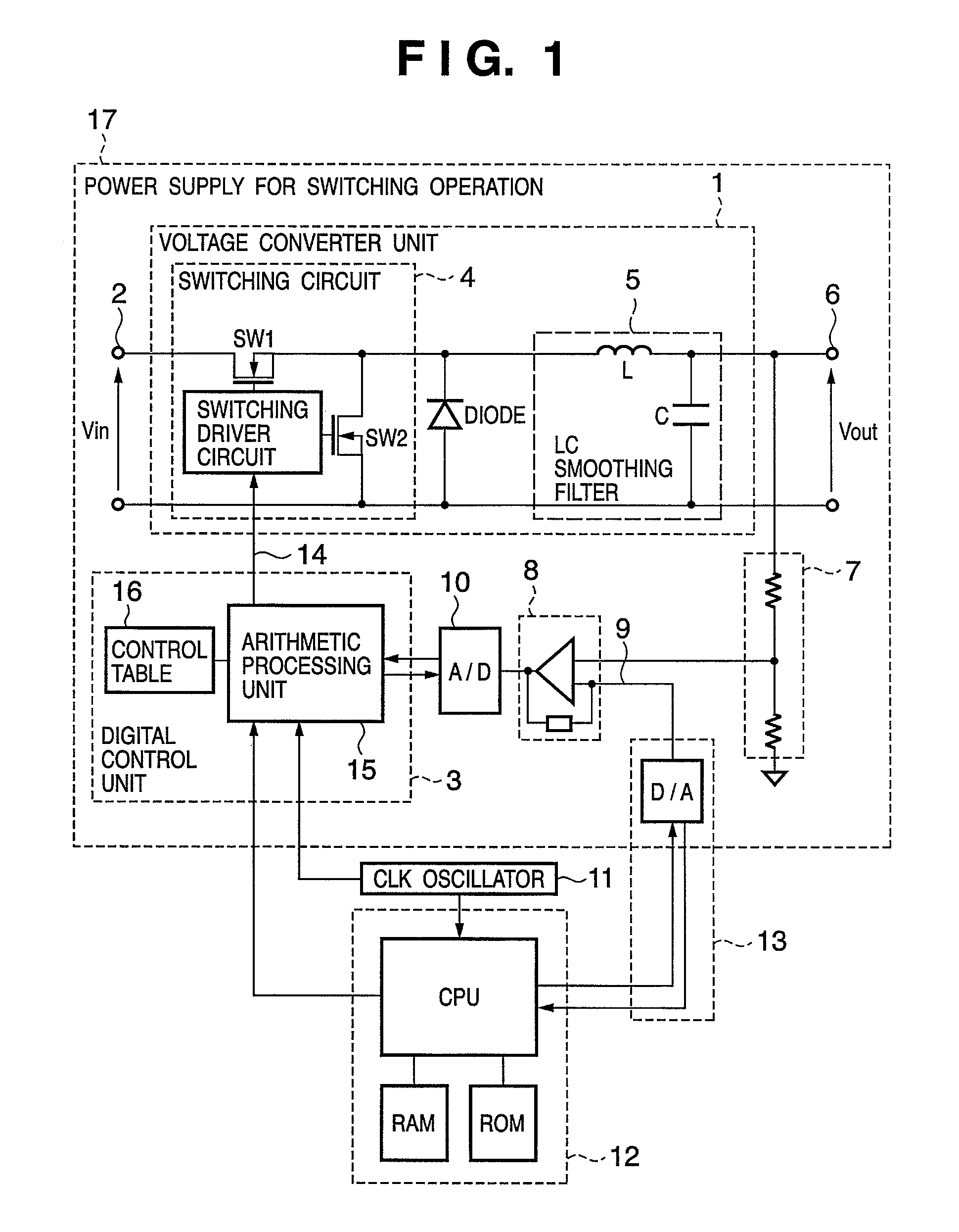
[0058]FIG. 1 is a block diagram showing the arrangement of a power supply for switching operation and part of an electronic apparatus including the power supply for switching operation according to the first embodiment of the present invention.

[0059]As shown in FIG. 1, a power supply 17 for switching operation includes a voltage converter unit 1 and digital control unit 3, and is controlled by signals from a clock (CLK) oscillator 11 and control device 12 of the electronic apparatus main body. The voltage converter unit 1 includes a switching circuit 4 and output circuit 5. The switching circuit 4 converts an input voltage Vin input to an input terminal 2 into intermittent pulse signals. The output circuit 5 converts a pulse signal output from the switching circuit 4 into a DC current, and outputs it as an output voltage Vout to an output terminal 6. The switching circuit 4 comprises power switching elements SW1 and SW2 such as MOSFETs, a switching driver circuit which drives the po...

second embodiment

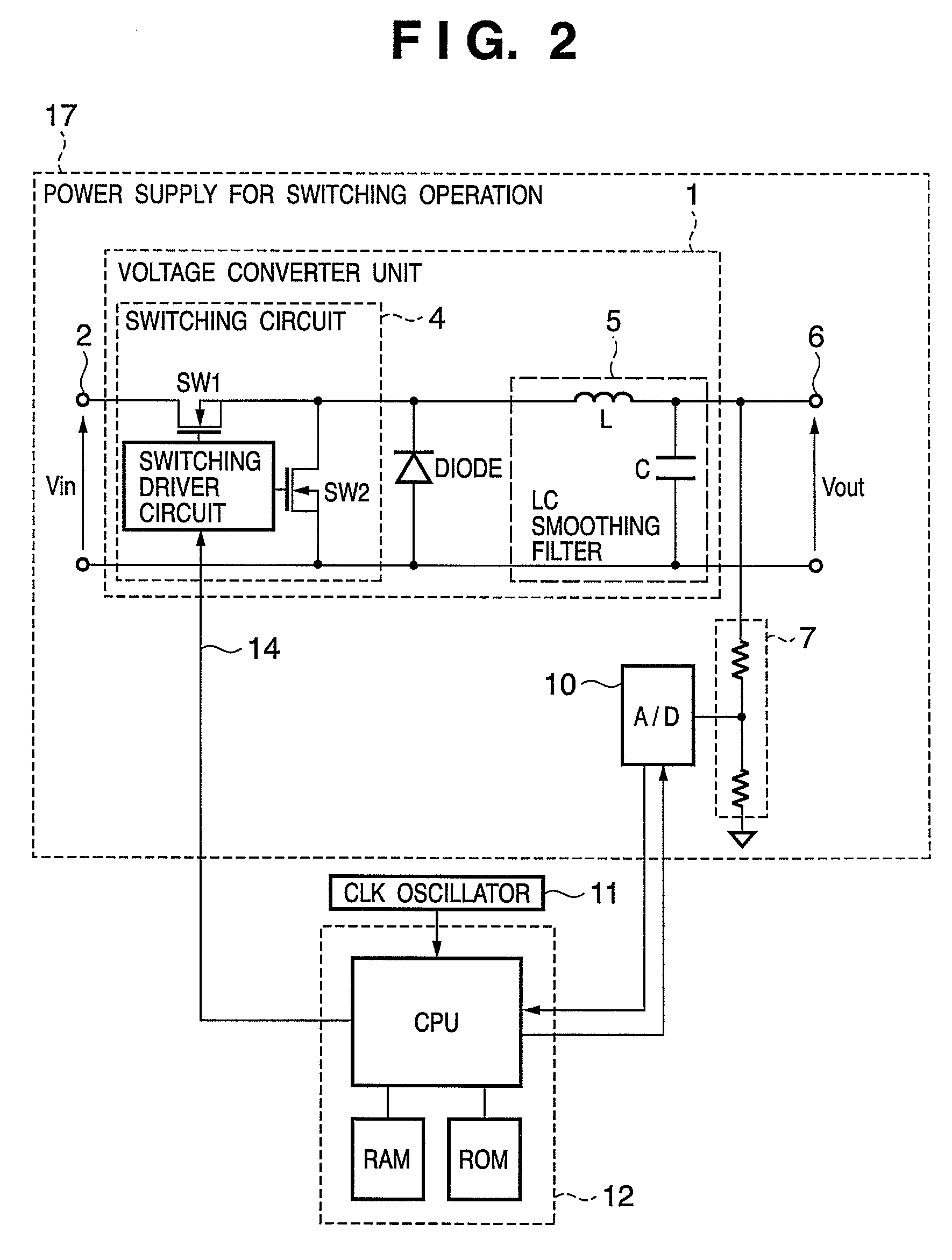
[0122]A power supply for switching operation according to the second embodiment of the present invention will be explained. The second embodiment is also related to a power supply for switching operation used in an electronic apparatus, similar to the first embodiment. In the following description, the same parts as those in the first embodiment will be omitted, and features of the second embodiment will be mainly explained.

[0123]FIG. 3 is a block diagram showing the arrangement of a power supply for switching operation and part of an electronic apparatus including the power supply for switching operation according to the second embodiment of the present invention.

[0124]In the first embodiment, the error amplifier 8 amplifies the error between the detection value of the output voltage detection circuit 7 and the reference voltage 9. The A / D converter 10 samples an output from the error amplifier 8 in a cycle instructed by the digital control unit 3, and outputs the sampling data to ...


PUM


Abstract

An object of this invention is to finely set the voltage at high speed without decreasing the efficiency. In a power supply for switching operation including a switching circuit, an output circuit, a control table which stores data on the ON and OFF periods of the switching circuit in correspondence with a set voltage, an arithmetic processing unit which performs reading operation from the control table and PWM operation, and a digital control unit which controls the switching circuit by outputting a PWM signal, feedback control based on the output voltage is performed in a case where the output voltage is not changed. When changing the output voltage, the feedback control is switched over to control based on data in the control table to change the output voltage at high speed.

Description

BACKGROUND OF THE INVENTION[0001]1. Field of the Invention[0002]The present invention relates to a power supply for switching operation, an electronic apparatus including the same, and a method of controlling the same. More specifically, this invention relates to an increase in response speed in a power supply for switching operation which can change an output voltage value to a plurality of values.[0003]2. Description of the Related Art[0004]A printer which prints information such as a desired character or image on a sheet-like print medium such as paper or a film is known as an information output apparatus for a wordprocessor, personal computer, facsimile apparatus, and the like.[0005]Although various methods are known as the printing method of this type of printer, an inkjet method has recently received a great deal of attention because it can perform non-contact printing on a print medium such as paper, can easily print in color, and is quiet. As an ink-jet arrangement, a serial...

Claims


Application Information

Patent Timeline
Patent Type & Authority Patents(United States)
IPC IPC(8): G05F1/56
CPCH02M3/157H02M3/1588Y02B70/1466Y02B70/10
Inventor NAGAI, MASAYUKI
Owner CANON KK
Learn More