Projector and optical device

a technology of optical devices and projectors, applied in static indicating devices, non-linear optics, instruments, etc., can solve the problems of significant physical change of solid-state light-emitting elements, non-uniform light intensity of projection images, and downsizing and weight reduction of projectors

Active Publication Date: 2004-12-30
SEIKO EPSON CORP
View PDF5 Cites 58 Cited by
  • Summary
  • Abstract
  • Description
  • Claims
  • Application Information

AI Technical Summary

Benefits of technology

[0013] According to an exemplary embodiment, the light source may include a plurality of solid-state light-emitting elements; the light-intensity measuring section may include a plurality of light-intensity measuring elements corresponding to the plurality of solid-state light-emitting elements; and the light-source controller may control each of the plurality of solid-state light-emitting elements. Since the light-receiving elements functioning as a light-intensity measuring section are arranged in the image forming position of the solid-state light-emitting elements or in the vicinity thereof, the light intensity for each of the plurality of solid-state light-emitting elements of the light source can be measured. The light intensity measurement of each solid-state light-emitting element allows the light intensity of the solid-state light-emitting elements to be stabilized and uniformized. Accordingly, a projector that forms a bright, stable, and uniform projection image is provided.
[0022] An aspect of the invention provides an optical device including a light source to emit light; a spatial light modulator to modulate the light from the light source in accordance with an image signal; and an imaging lens to image the light modulated by the spatial light modulator onto a specified surface. The spatial light modulator is a tilt mirror device including a movable mirror element reflecting the light from the light source in the direction of the imaging lens or in the direction other than that of the imaging lens. The optical device further includes: a light-intensity measuring section provided in an imaging position of the light source or in the vicinity of the imaging position to measure the light intensity of the light reflected in the direction other than that of the projector lens; and a light-source controller to control the light source in accordance with the signal from the light-intensity measuring section. Accordingly, an effective and stable optical device is provided in which the light intensity of the light source can be stabilized without decreasing efficiency.

Problems solved by technology

Ultrahigh pressure mercury lamps which have been used as a light source can emit high-intensity light but require large and heavy drive circuits, thus preventing the downsizing and weight reduction of the projectors.
When a plurality of solid-state light-emitting elements are used in the projectors to obtain sufficient light intensity, the variations in light intensity of the solid-state light-emitting elements cause non-uniform light intensity of the projection images.
The large outputs cause significant physical change of the solid-state light-emitting elements due to heat generation over their lifetime.
The above-mentioned drive-current control method of stabilizing the output by the constant-current driving or sensing the electrical condition cannot cope with the physical changes of the solid-state light-emitting elements, having difficulty in sufficiently stabilizing the light quantity.
However, in the projector, when light-receiving elements to monitor light intensity are arranged near the light sources, the light is blocked off by the light-receiving elements to disadvantageously make the projection images dark.
Also, when the light-receiving element to monitor light intensity is arranged in the vicinity of each of the solid-state light-emitting elements to stabilize the light intensity of each solid-state light-emitting element and to uniformize the luminance of the solid-state light-emitting elements, the structure becomes more complicated, making it difficult to dispose.
The light reflected toward the projection lens forms a projection image, while the light reflected in the direction other than that of the projector lens is wasted.
Since the movable range of the movable mirror elements is limited, the light deflection angle of the spatial light modulator is also limited.

Method used


Image

  • Projector and optical device
  • Projector and optical device
  • Projector and optical device

Examples


first exemplary embodiment

[0038] First Exemplary Embodiment

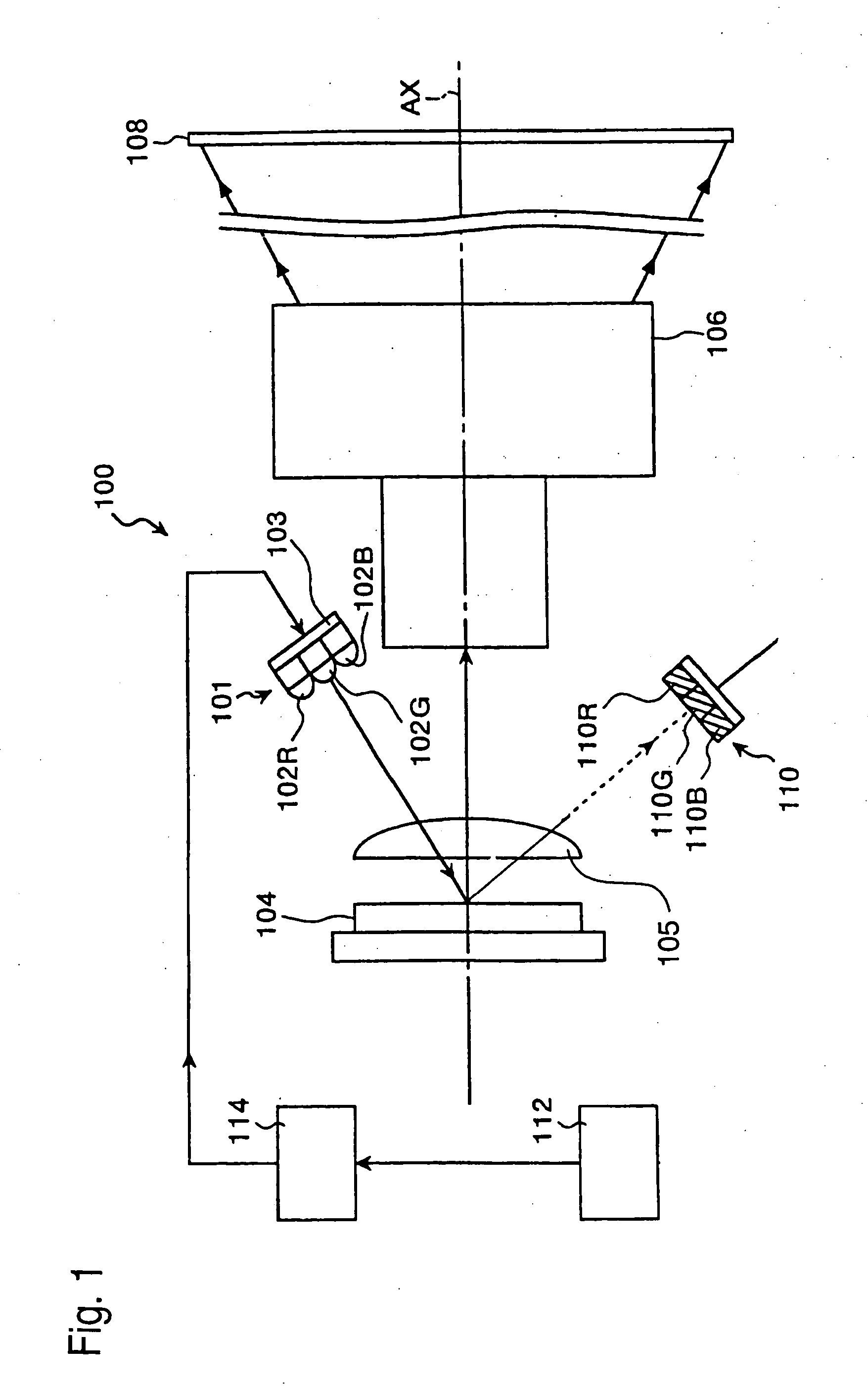
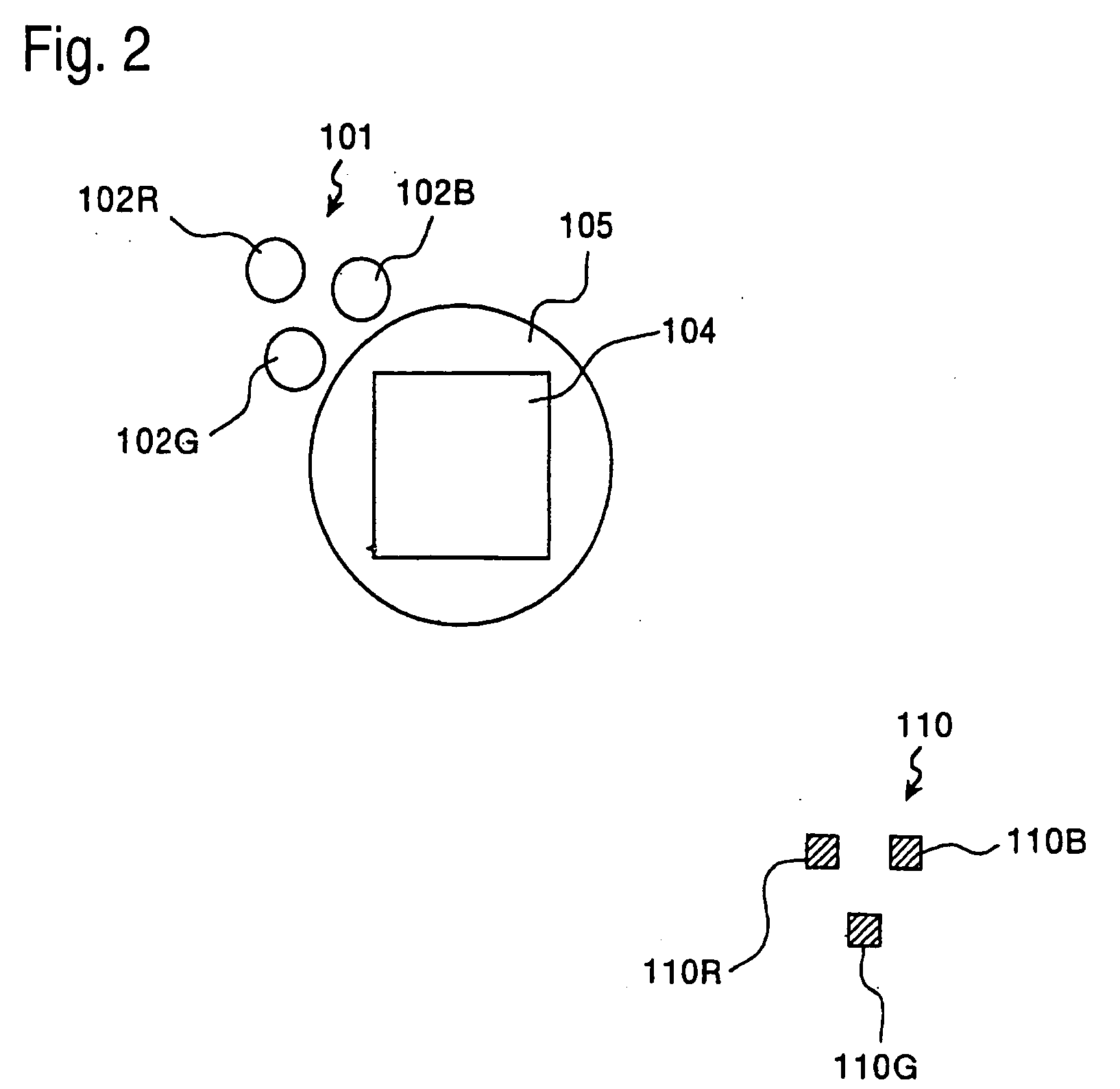
[0039] FIG. 1 shows a schematic of a projector 100 according to a first exemplary embodiment of the present invention. A light source 101 of the projector 100 includes a plurality of light-emitting diodes (hereinafter, "LED") which are solid-state light-emitting elements. The LEDs of the light source 101 are driven by a light-source drive circuit 103. The LEDs include an R-light LED 102R that emits red light (hereinafter, s "R-light"), a G-light LED 102G that emits green light (hereinafter, "G-light"), and a B-light LED 102B that emits blue light (hereinafter, "B-light").

[0040] The light emitted from the light source 101 passes through a field lens 105 and is then incident on a spatial light modulator 104. The field lens 105 has the function of illuminating the spatial light modulator 104 in a telecentric manner. Specifically, the function of letting the illumination light into the spatial light modulator 104 as parallel as possible to a principal ra...

second exemplary embodiment

[0059] Second Exemplary Embodiment

[0060] FIG. 5 shows a schematic of a projector 500 according to a second exemplary embodiment of the invention. The same components as those of the first exemplary embodiment are given the same reference numerals and their redundant description will be omitted. A light source 501 of the projector 500 includes a first light source 501RB that emits light in a first wavelength range and a second light source 501G that emits light in a second wavelength range different from the first wavelength range. The light source 501 denotes both of the first light source 501RB and the second light source 501G hereinafter. The first light source 501RB includes an R-light LED 502R that emits R-light and a B-light LED 502B that emits B-light. The second light source 501G includes G-light LEDs 502G that emit G-light. The first light source 501RB and the second light source 501G are arranged in approximately symmetrical positions with respect to the optical axis AX of ...

third exemplary embodiment

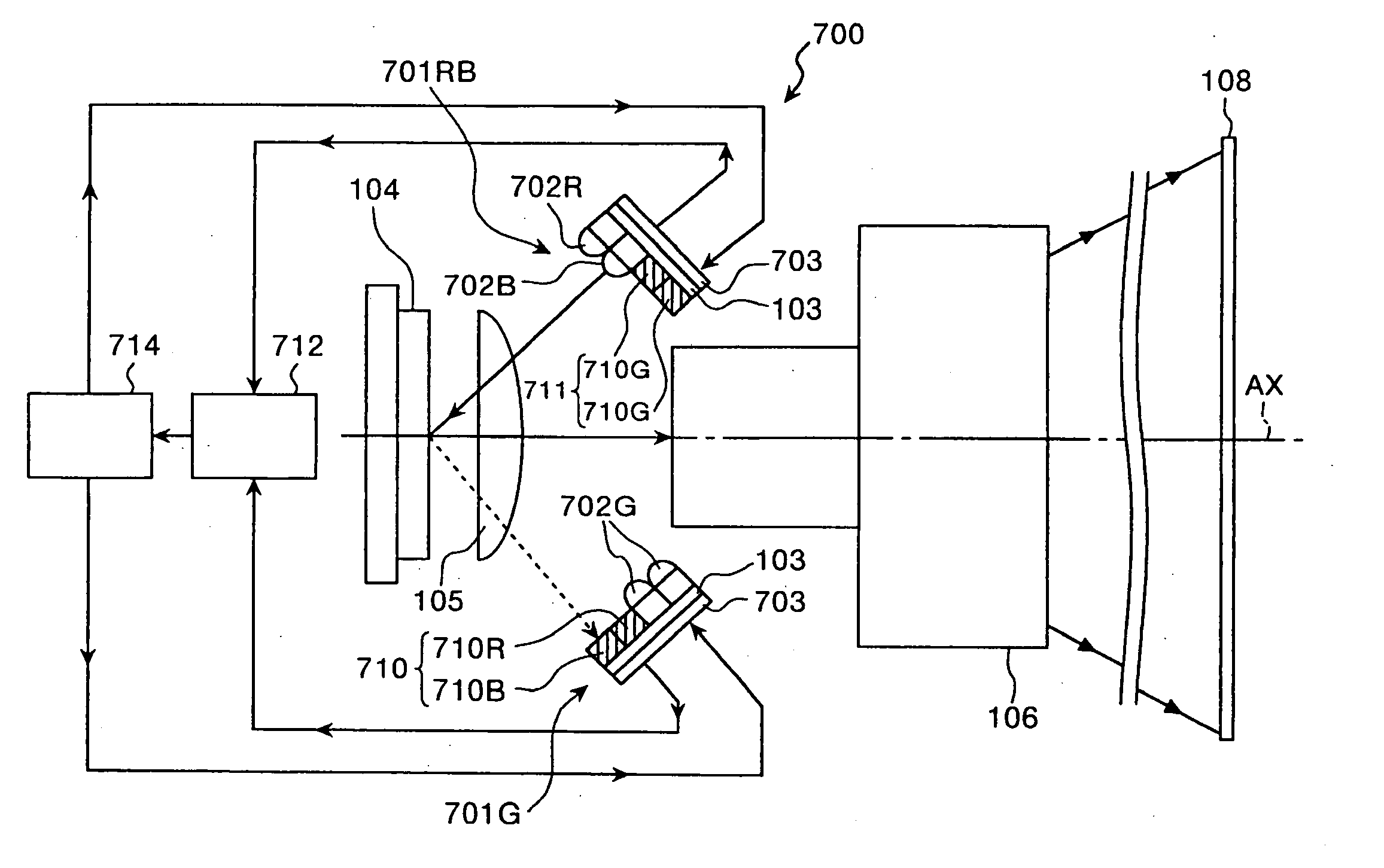
[0074] Third Exemplary Embodiment

[0075] FIG. 7 is a schematic of a projector 700 according to a third exemplary embodiment of the invention. The same components as those of the first exemplary embodiment are given the same reference numerals and their redundant description will be omitted. The light source of the projector 700 according to the exemplary embodiment includes a first light source 701RB that emits light in a first wavelength range and a second light source 701G that emits light in a second wavelength range different from the first wavelength range as in the second exemplary embodiment. The first light source 701RB includes an LED 702R that emits R-light and an LED 702B that emits B-light. The second light source 701G includes LEDs 702G that emit G-light. The first light source 701RB and the second light source 701G are arranged in approximately symmetrical positions with respect to the optical axis AX of the projector lens 106.

[0076] The first light source 701RB and a s...


PUM

PropertyMeasurementUnit
inclination anglesaaaaaaaaaa
light intensityaaaaaaaaaa
wavelength rangeaaaaaaaaaa

Abstract

To provide a projector or the like, which use a solid-state light-emitting element as light source and which provides a bright, stable, and uniform projection image, the present invention includes: a light source to emit light; a spatial light modulator to modulate the light from the light source in accordance with an image signal; and a projector lens to project the light modulated by the spatial light modulator. The spatial light modulator is a tilt mirror device including a movable mirror element that reflects the light from the light source in the direction of the projector lens or in the direction other than that of the projector lens. The invention may further include a light-intensity measuring section provided in an imaging position of the light source or in the vicinity of the imaging position to measure the light intensity of the light reflected in the direction other than that of the projector lens; and a light-source controller to control the light source in accordance with the signal from the light-intensity measuring section.

Description

[0001] 1. Field of Invention[0002] The present invention relates to a projector and, more particularly, to a projector and an optical device using a solid-state light-emitting element as light source.[0003] 2. Description of Related Art[0004] Since solid-state light-emitting elements, such as light-emitting diode elements and semiconductor laser devices, have extremely high efficiency of converting electricity to light and are compact and lightweight, they have wide applicability in lighting. Related art or known methods of controlling the light intensity of the solid-state light-emitting elements include an electrical feedback method by constant-current driving or the like (for example, see JP-A-1-116692, JP-A-63-307784 and JP-A-63-226079) and a feedback control method by measuring light intensity (for example, see JP-A-1-239969, JP-U-62-071642 and JP-A-63-027073).[0005] Projectors are devices that display images by projecting light (projection light) in accordance with image signa...

Claims


Application Information

Patent Timeline
Patent Type & Authority Applications(United States)
IPC IPC(8): G02B27/18G02F1/13G02B26/08G02F1/133G02F1/1335G02F1/13357G03B21/00G03B21/14G03B21/18G03B21/20G03B21/26G03B21/28H05B37/02
CPCG03B21/14G03B21/26H04N9/3111H04N9/3155H04N9/3164H04N9/3197G03B21/2033G03B21/2053G03B21/008
Inventor SEKI, HIDEYAYAMAGUCHI, KAORU
Owner SEIKO EPSON CORP
Why Eureka
Try Eureka