Optical arrangement for assay reading device

a technology of optical arrangement and reading device, which is applied in the direction of measurement device, material analysis, instruments, etc., can solve problems such as the degree of subjectivity

Active Publication Date: 2008-01-01
ABBOTT RAPID DIAGNOSTICS INT UNLTD
View PDF57 Cites 81 Cited by
  • Summary
  • Abstract
  • Description
  • Claims
  • Application Information

AI Technical Summary

Benefits of technology

[0010]The present disclosure provides inexpensive, typically disposable, assay readers either for use with, or in integral combination with, an assay test strip such as disclosed by EP291194. The optics are provided in a compact arrangement well-suited, for example, for a handheld device. The arrangement also provides an optimal or near optimal path length between the light source and photodetector thus establishing a strong signal.

Problems solved by technology

This introduces a degree of subjectivity, which is undesirable.
Thus there is a requirement for the user to carefully align the test stick with the assay result reader which, especially for devices intended to be used in the home, can be problematic.

Method used


Image

  • Optical arrangement for assay reading device
  • Optical arrangement for assay reading device
  • Optical arrangement for assay reading device

Examples


example 1

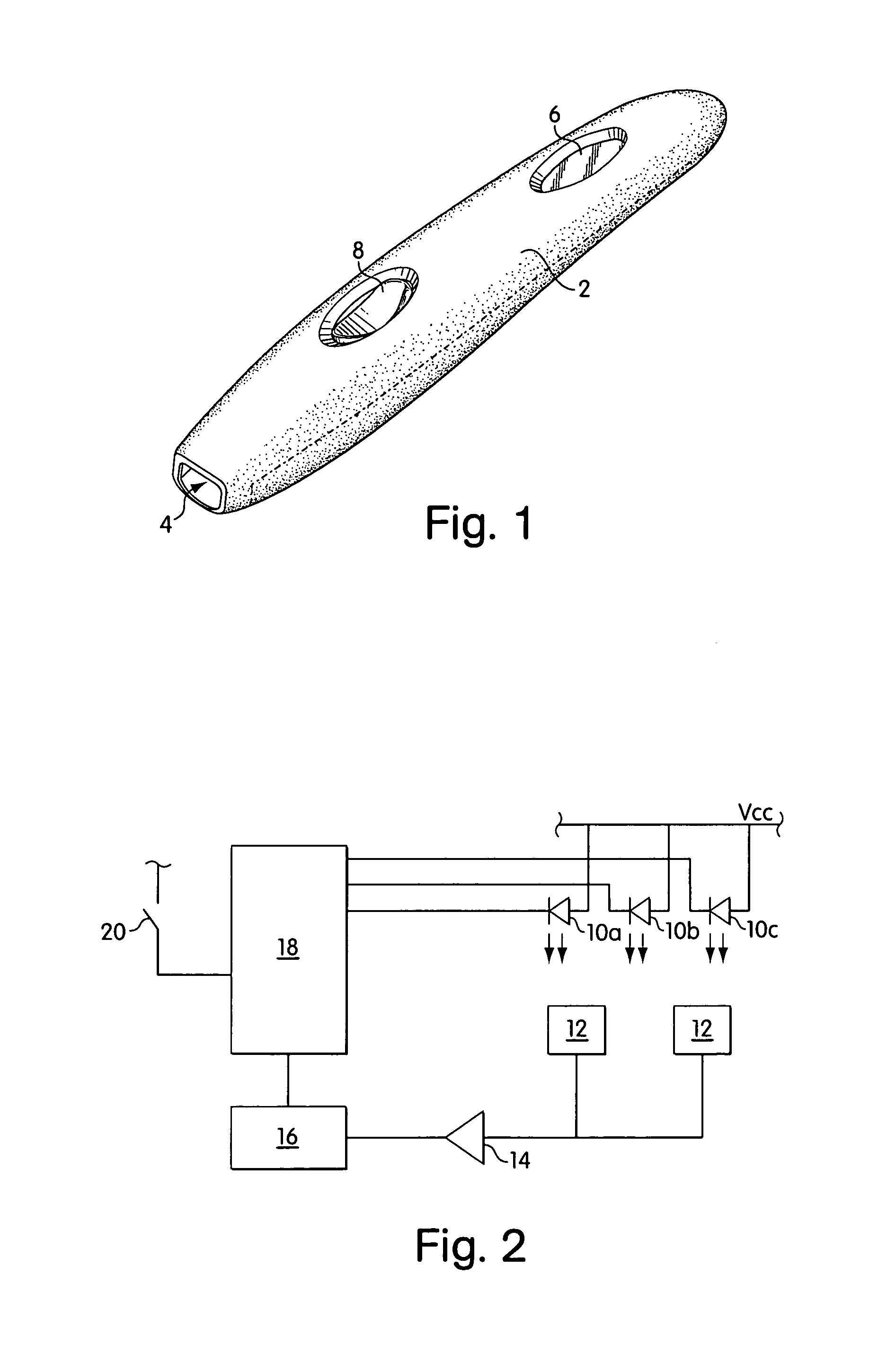
[0042]An embodiment of an assay result reading device having both “shared” photodetectors and “commonly read” zones is illustrated in FIG. 1.

[0043]The reading device is about 12 cm long and about 2 cm wide and is generally finger or cigar-shaped. In preferred embodiments, the housing is no larger than about 12 cm long, about 2.5 cm wide, and about 2.2 cm tall. However, any convenient shape may be employed, such as a credit card shaped reader. The device comprises a housing 2 formed from a light-impermeable synthetic plastics material (e.g. polycarbonate, ABS, polystyrene, high density polyethylene, or polypropylene or polystyrol containing an appropriate light-blocking pigment, such as carbon). At one end of the reading device is a narrow slot or aperture 4 by which a test strip (not shown) can be inserted into the reader.

[0044]On its upper face the reader has two oval-shaped apertures. One aperture accommodates the screen of a liquid crystal display 6 which displays information to ...

example 2

[0055]This example described in greater detail the features of the preferred arrangement of LED's and photodiodes outlined in Example 1.

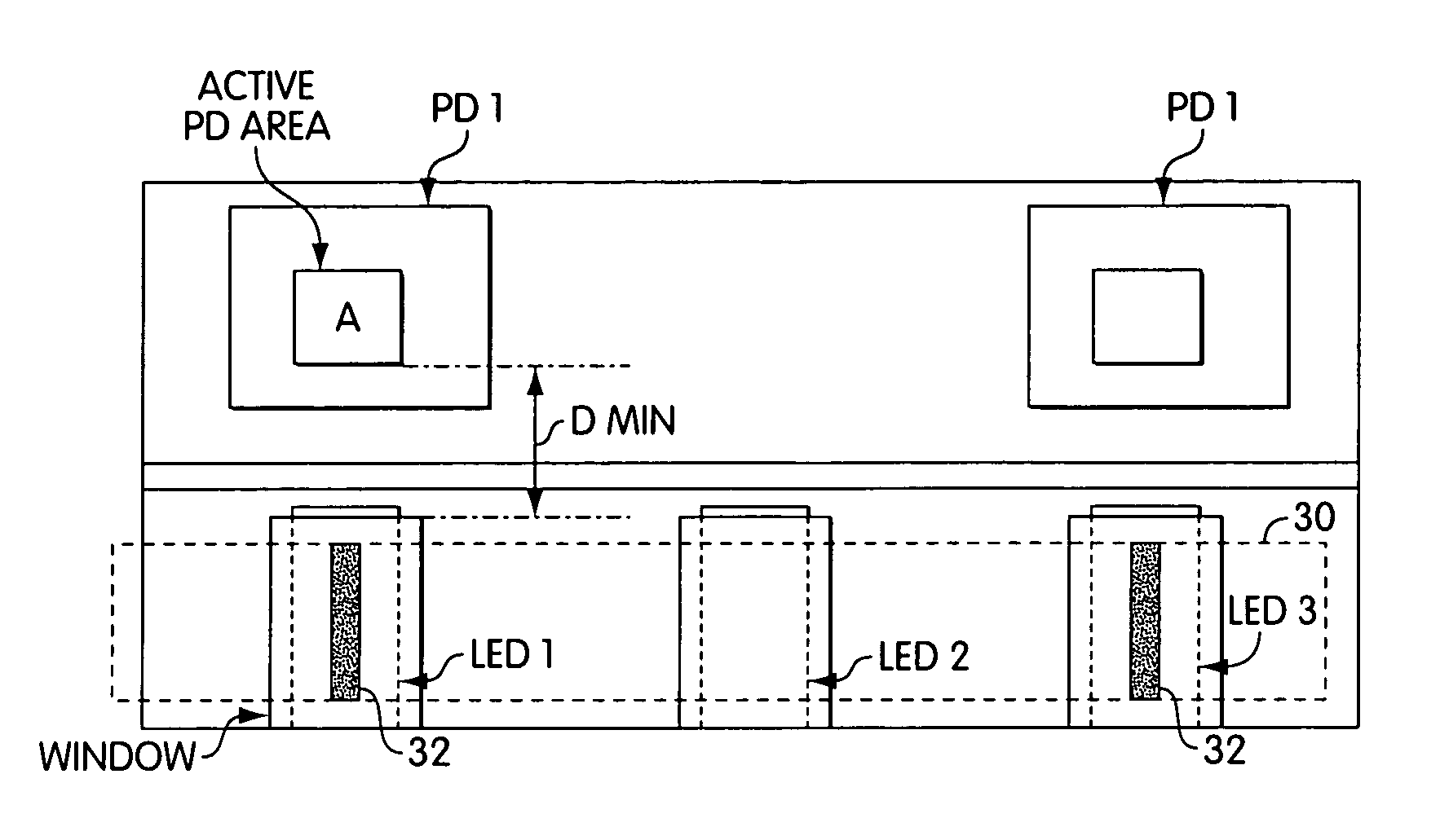
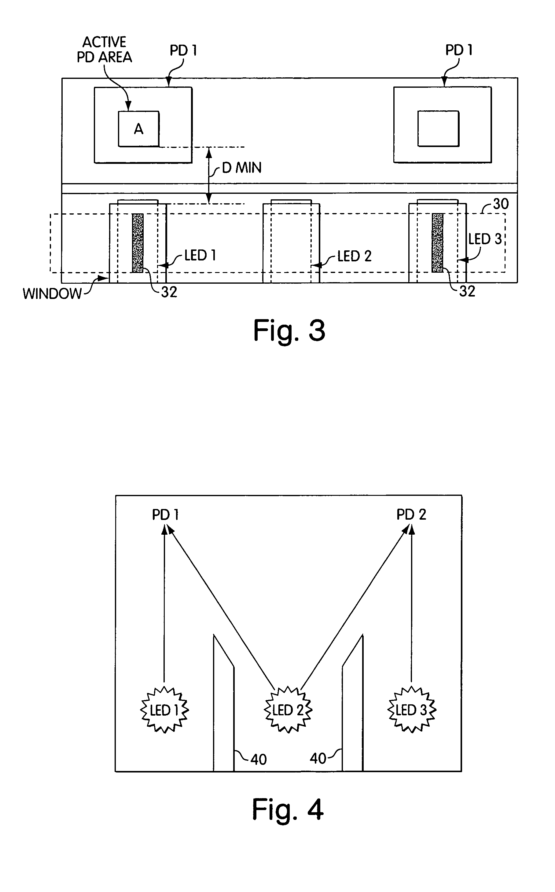
[0056]FIG. 3 shows a plan view of an exemplary embodiment of an optical arrangement. In this embodiment, the optical arrangement include three light emitting diodes and two photodetectors. The active area (A) of the photodetectors (PD) is 1.5 mm×1.5 mm. The optics are arranged such that center lines of LED's 1 and 3 correspond to the center lines of PD 1 and PD2. The 3 LED's and two photodetectors are disposed within an area no larger than about 1 square cm, preferably no larger than about 0.7 square cm, specifically 1 cm×0.7 cm.

[0057]Also shown is the position of the test-strip 30 that is positioned above the LED's. The test-strip is inserted so that the test and control lines 32 are situated above respectively LED's 1 and 3. The distance D, namely the distance between the PD and LED, is preferably large enough to prevent specular reflection of lig...

example 3

[0067]In one exemplary embodiment, the active area of the photodetector is 2 mm×2 mm. The light source provides light, at least some of which has a wavelength of 635 nm. The height of the test-strip above the light source is 5.5 mm. The wall height separating the LED's is 2.7 mm and the angle of the wall is 30 degrees. The plastic used is black nylon.


PUM

PropertyMeasurementUnit
areaaaaaaaaaaa
areaaaaaaaaaaa
areaaaaaaaaaaa

Abstract

Disclosed, in one aspect, is an assay result reading device for reading the result of an assay performed using a test strip, the device comprising: a light source or sources, said light source / s emitting light incident upon at least two, spatially separated zones of the test strip; and a photodetector which detects light emanating from each of the two said zones; in a further aspect is disclosed an assay result reading device for reading the result of an assay performed using a test strip, the device comprising: at least one light source incident upon a zone of the test strip; and at least two photodetectors both of which are able to detect some of the light emanating from the zone of the test strip illuminated by the light source.

Description

CROSS-REFERENCE TO RELATED APPLICATION[0001]This application claims the benefit of U.S. Provisional Patent Application Ser. No. 60 / 508,001, filed Oct. 2, 2003, the entire contents of which are hereby incorporated herein by this reference.FIELD[0002]The disclosed subject matter relates to assay reading devices for the measurement of analytes. In particular it relates to electronic readers for use with assay test-strips which use optical methods of measurement.INTRODUCTION[0003]Disposable analytical devices suitable for home testing of analytes are now widely commercially available. A lateral flow immunoassay device suitable for this purpose for the measurement of the pregnancy hormone human chorionic gonadotropin (hCG) is sold by Unipath under the brand-name CLEARBLUE® and is disclosed in EP291194.[0004]EP291194 discloses an immunoassay device comprising a porous carrier containing a particulate labelled specific binding reagent for an analyte, which reagent is freely mobile when in ...

Claims


Application Information

Patent Timeline
Patent Type & Authority Patents(United States)
IPC IPC(8): G01N21/00G01N21/47G01N21/86
CPCG01N21/4738G01N21/8483
Inventor PHELAN, ANDREW PETERSHARROCK, STEPHEN PAUL
Owner ABBOTT RAPID DIAGNOSTICS INT UNLTD
Why Eureka
Try Eureka