Metal spin forming head

a metal spin forming and head technology, applied in the field of metal spin forming head, can solve the problems of limited use of such a forming technique in many other fields, process is even slower, and single roller spin forming system requires a relatively large amount of time per unit, so as to achieve rapid and accurate spin forming

Inactive Publication Date: 2008-01-08
SCHALLER & CO
View PDF31 Cites 30 Cited by
  • Summary
  • Abstract
  • Description
  • Claims
  • Application Information

AI Technical Summary

Benefits of technology

[0037]The present metal spin forming head is configured to provide much more rapid and accurate spin forming of metal tubes and similar workpieces. While the present spin forming head may be adapted for use in spin forming a generally tubular shape of any practicable size and for any practicable purpose, it is particularly well suited for forming shells or housings for catalytic converters in automotive exhaust systems.
[0038]The present spin forming head includes a series of separate spin forming rollers or wheels comprising at least two sets. The first set comprises a series (preferably four, more or less) of relatively wide edged rollers evenly spaced about the inner circumference of the tool head and about the outer circumference of the workpiece. These first rollers accomplish most of the shaping of the workpiece, working it to the generally desired diameter at the generally desired locations along the length of the workpiece. The second roller set comprises a series of rollers each circumferentially spaced between two of the first series rollers. The second set rollers may be displaced from coplanar alignment with the first set rollers. The second or finishing series of rollers each have relatively narrower or sharper edges, and provide for the forming of relatively sharp creases or circumferential grooves in the workpiece. These circumferential indentations result in corresponding circumferential ridges within the workpiece, which serve to secure an article (e.g., catalytic converter element) immovably within the shell, without need for mechanical fastening means.
[0040]The programmable logic control used to position the multiple rollers of the present spin forming head, is able to provide sufficiently rapid actuation of each of the rollers so as to actuate the rollers cyclically during the rotation of the workpiece within the head (or alternatively, the rotation of the head about the stationary workpiece). Thus, any of the rollers may be driven down (e.g., via conventional hydraulic or other actuating means) at one specific point or area about the circumference of the workpiece at each revolution of the workpiece (or head, if the head is being rotated), to form a shape having a non-cylindrical cross section. The present metal spin forming head with its programmable logic control is thus capable of forming virtually any practicable shape which may be formed from a cylindrical tube.

Problems solved by technology

The use of a single roller, and the circular cross-sectional shapes formed by conventional spin forming processes, greatly limits the use of such a forming technique in many other fields.
The single roller spin forming system requires a relatively large amount of time per unit, and is generally limited to forming circular cross sectional shapes.
Moreover, the process is even slower when harder and more difficult to work metals are used for the workpiece.
Other techniques have been used, such as the so-called “tourniquet wrap,” but each of these techniques requires that the seams along the edges of the metal shell component(s) be welded, which requires an additional step and additional time in manufacture.
Slight exhaust leaks can result in anomalous readings in the on-board diagnostic systems with which all automobiles are presently equipped, as well as the possibility of exhaust leaks into the passenger compartment of the vehicle.
These hazards increase over time, as welds are generally prone to attack by road salts and other environmental hazards during the life of the vehicle.
It can be extremely difficult for an automotive exhaust manufacturer to produce a leakproof exhaust component which will remain roadworthy for the federally required 50,000 mile minimum life span for emissions control components, and this minimum distance is doubled 1o 100,000 miles in some areas.
The final result is a weldless, seamless housing or shell having any desired external contour as required according to the internal componentry installed therein and the external space and installation limitations for the device.
The De Sousa et al. roller head can only form a single conically shaped end on a tube; it cannot be adapted to form other shapes or to neck down a tube at some intermediate point(s) along its length.
Moreover, De Sousa et al. do not disclose any form of cyclic operation for their spin forming head.
This is accomplished by means of a programmable logic control; Hamstra et al. do not disclose such a means of controlling the movement of the rollers in their spin forming head.
However, the Li et al. system is relatively slow, as it utilizes only a single roller.

Method used


Image

  • Metal spin forming head
  • Metal spin forming head
  • Metal spin forming head

Examples


Embodiment Construction

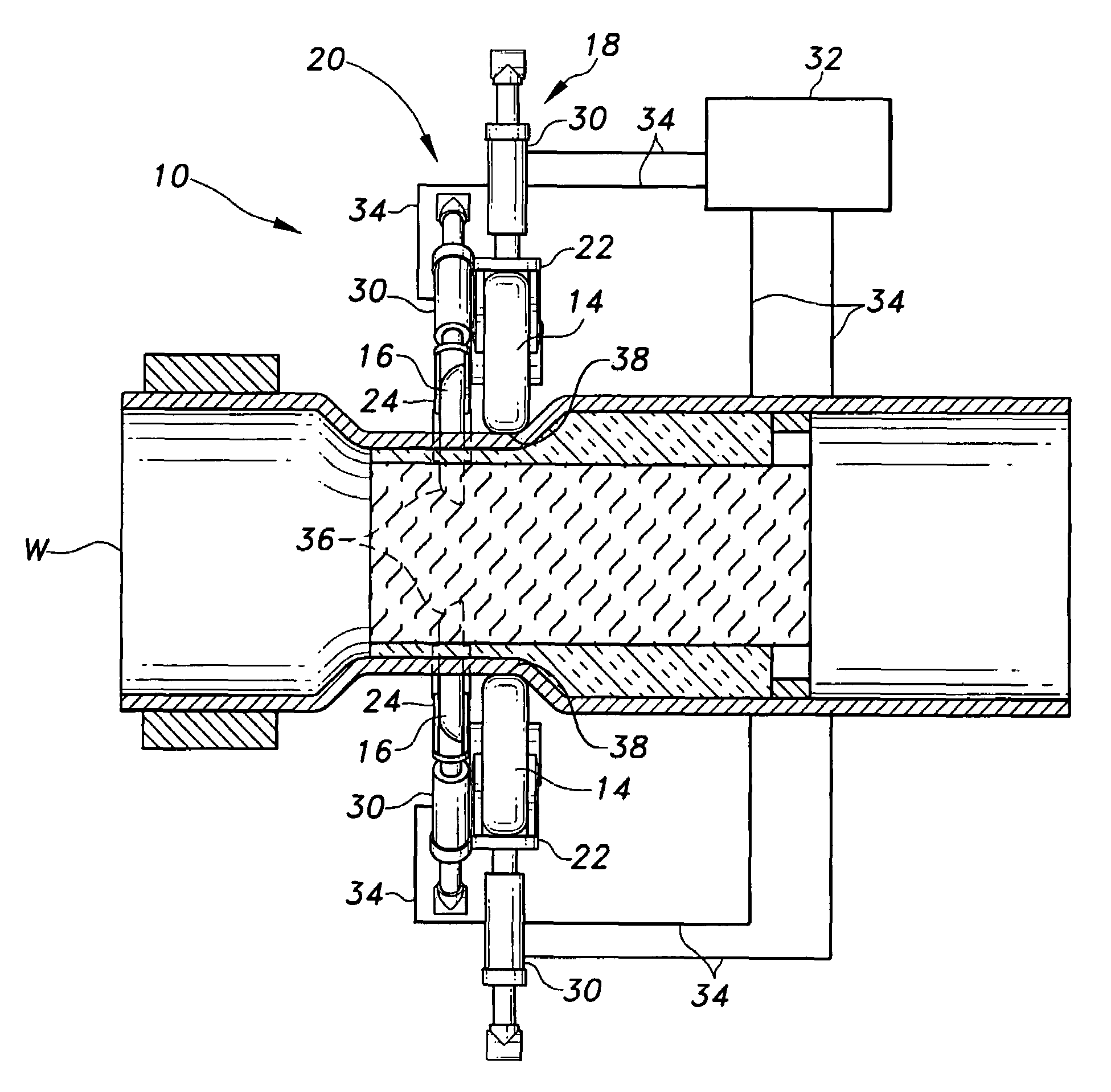
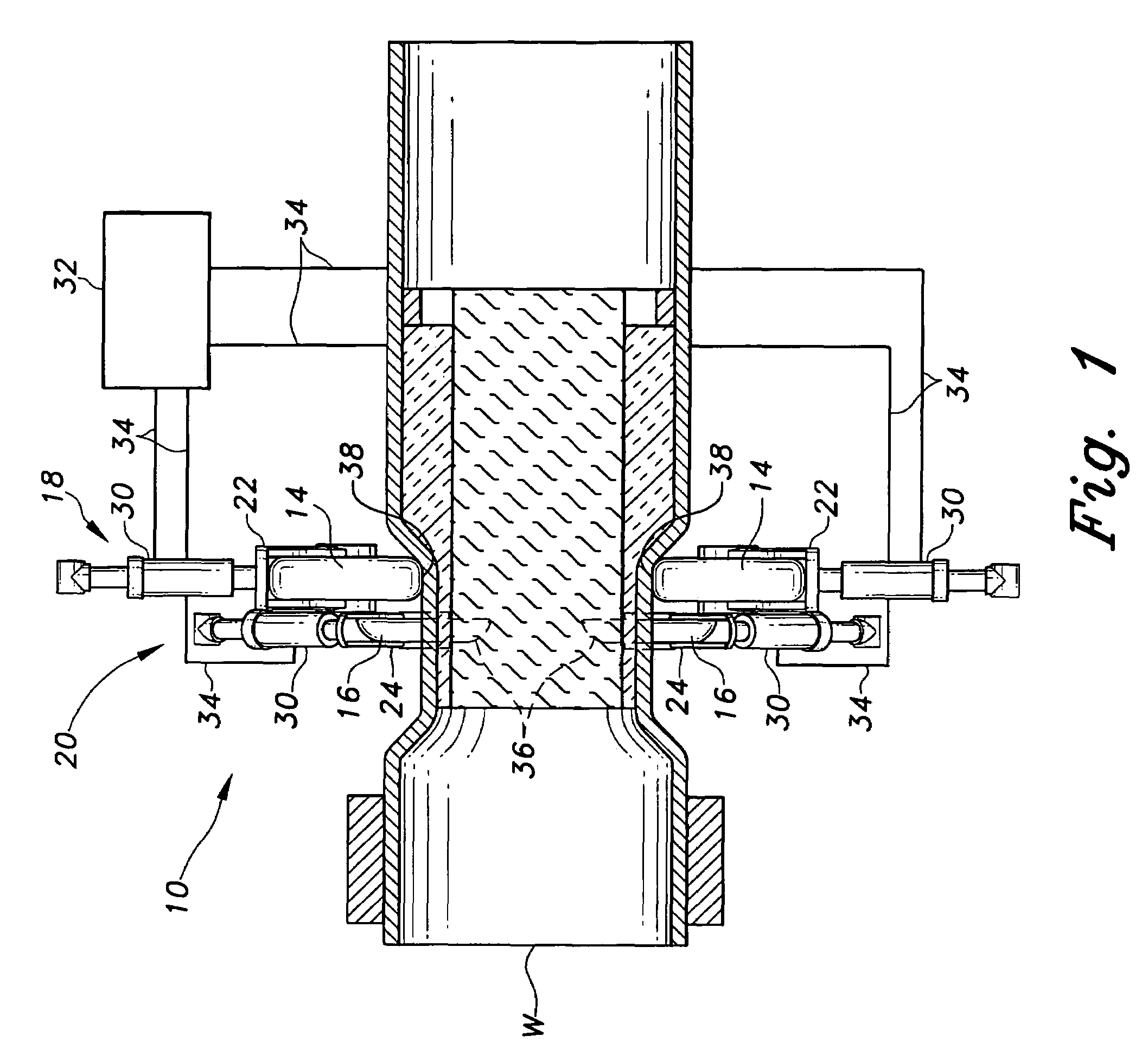
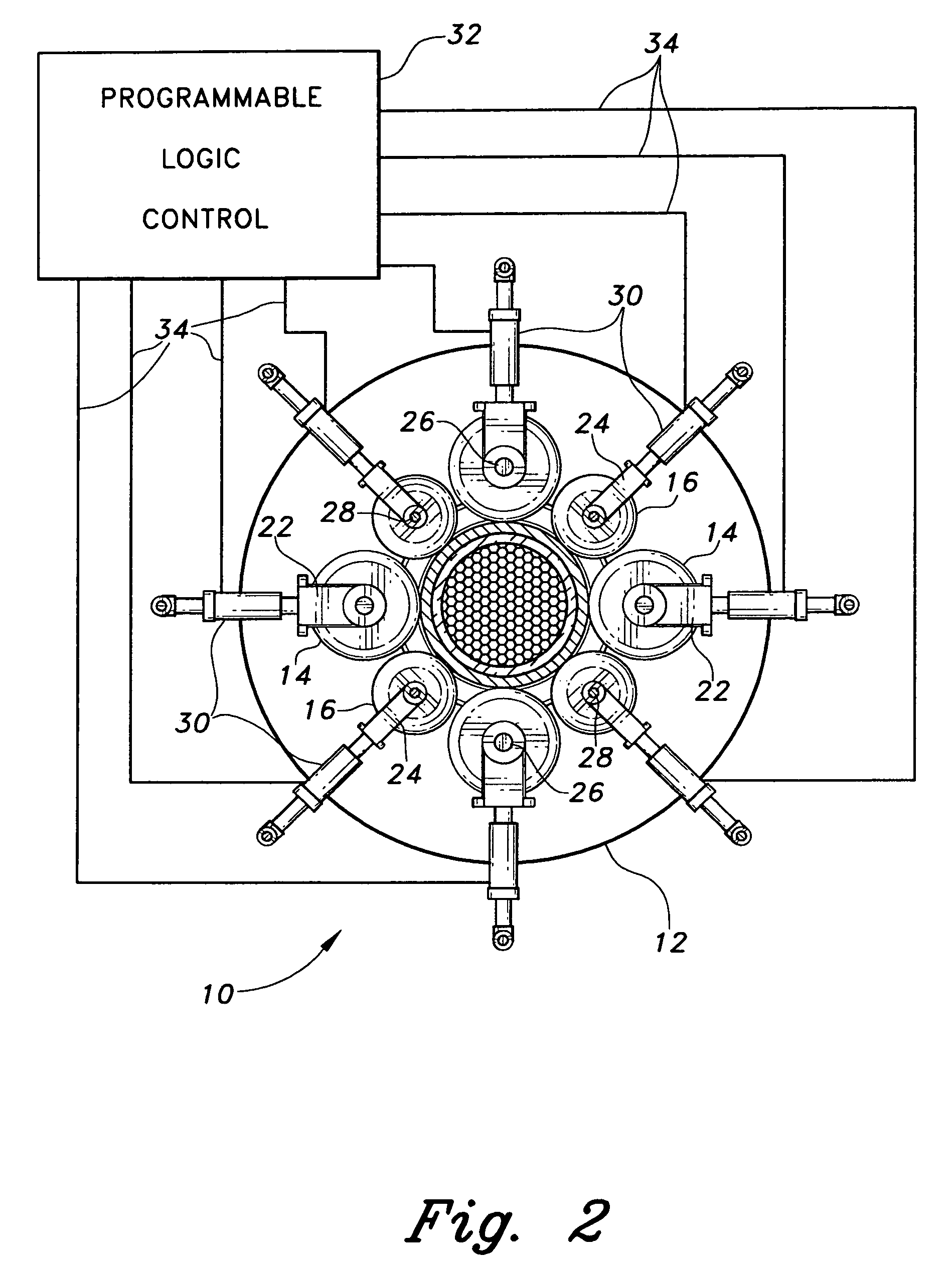
[0048]The present invention comprises a head assembly for spin forming tubular metal components. The present metal spin forming head incorporates numerous features and advantages not provided in earlier developed devices of the related art. The present spin forming head is capable of forming relatively narrow circumferential grooves about the workpiece, which result in corresponding circumferential beads in the interior of the workpiece. These circumferential beads serve to secure an internal element, e.g. a catalytic converter element within a catalytic converter shell, within the tubular component. Moreover, the present spin forming device is capable of forming finished shapes having non-circular cross sections, due to the cyclic actuation of the rollers made possible by the programmable logic control which controls the system.

[0049]FIG. 1 of the drawings provides a schematic side elevation view in section of the present invention, shown positioned upon a tubular metal workpiece W...


PUM

PropertyMeasurementUnit
distanceaaaaaaaaaa
distanceaaaaaaaaaa
widthaaaaaaaaaa

Abstract

The present metal spin forming head includes two sets of rollers, with each set having a series of individual metal working rollers therein. The rollers of each set are circumferentially spaced evenly about the head, with each of the rollers of the second set being evenly positioned between corresponding rollers of the first set. The second roller set may be in a non-coplanar relationship with the first roller set. The first roller set comprises rollers having relatively broad widths, for forming the general contours of the workpiece. The second roller set comprises rollers having relatively narrow rims for forming circumferential grooves in the workpiece, resulting in corresponding beads within the workpiece for securing an article therein. The rollers are controlled independently of one another by a programmable logic control capable of driving the rollers cyclically as the workpiece (or spin forming head) rotates to form non-cylindrical shapes.

Description

BACKGROUND OF THE INVENTION[0001]1. Field of the Invention[0002]The present invention relates generally to machinery and methods for spin forming metal tubes, pipes, circular sheet stock, and the like to form different diameters and shapes thereon. More specifically, the present invention comprises a multiple roller spin forming head in which a series of primary forming rollers are followed by a series of secondary or finishing rollers. The secondary rollers generally have a narrower width, thereby permitting the formation of relatively abrupt changes in diameter or shape for the workpiece. The present system utilizes a programmable logic circuit to control the individual rollers, with the system also providing for selective cyclic control of the rollers relative to workpiece rotation to allow non-circular cross sections to be shaped.[0003]2. Description of the Related Art[0004]The basic principle of spin forming has been known for several decades. This metal forming principle utili...

Claims


Application Information

Patent Timeline
Patent Type & Authority Patents(United States)
IPC IPC(8): B21D22/14B21D22/00B21D22/16
CPCB21D22/16
Inventor LANCASTER, PAUL B.
Owner SCHALLER & CO
Why Eureka
Try Eureka