

Valve cover assembly for a vehicle engine and method for producing same
a technology for vehicle engines and valve covers, applied in the field of vehicle engines, can solve problems such as adding undesirable additional time and cos
- Summary
- Abstract
- Description
- Claims
- Application Information
AI Technical Summary
Benefits of technology
Problems solved by technology
Method used
Image

Examples
first embodiment
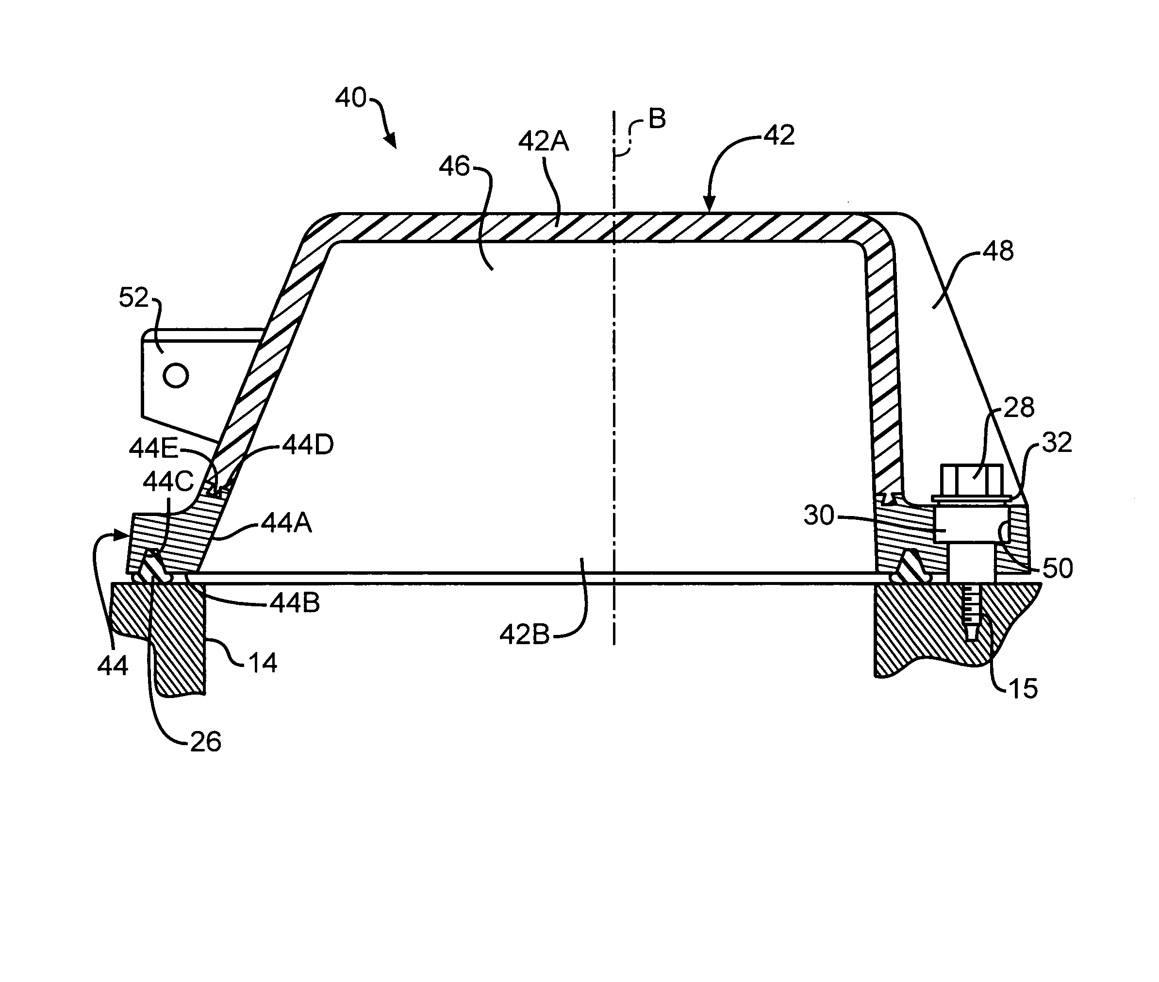
[0019]Referring now to FIG. 3 and using like reference numbers to indicate corresponding parts, there is illustrated a valve cover assembly, indicated generally at 40, in accordance with the present invention. The illustrated valve cover assembly 40 is preferably adapted for use on an internal combustion vehicle engine (only a portion of which is illustrated). The valve cover assembly 40 may, however, be used with other types of engines if so desired. In the illustrated embodiment, the valve cover assembly 40 is intended for mounting on the cylinder head 14 of an engine block (not shown).
[0020]The valve cover assembly 40 includes a valve cover body 42 and an attachment member or hold down flange 44. The valve cover body 42 defines a chamber 46 and a vertical axis B and has a closed end 42A, an opened end 42B. One or more strengthening ribs 48 may extend generally outwardly from an outer surface of the valve cover body 42. One or more fastener or bolt holes 50 (only one of such bolt ...
second embodiment
[0030]Referring now to FIGS. 4 and 4A and using like reference numbers to indicate corresponding parts, there is illustrated a valve cover assembly, indicated generally at 60, in accordance with the present invention. The illustrated valve cover assembly 60 is preferably for use on an internal combustion vehicle engine (only a portion of which is illustrated). The valve cover assembly 60 may, however, be used with other types of engines if so desired. In the illustrated embodiment, the valve cover assembly 60 is intended for mounting on the cylinder head 14 of an engine block (not shown).
[0031]The valve cover assembly 60 includes a valve cover body 62 and an attachment member or hold down flange 64. The valve cover body 62 defines a chamber 66 and a vertical axis C and has a closed end 62A and an opened end 62B. One or more strengthening ribs 68 may extend generally outwardly from an outer surface of the body 62. A sealing flange 70 extends generally axially outwardly from the body ...
third embodiment
[0041]Referring now to FIG. 5 and using like reference numbers to indicate corresponding parts, there is illustrated a valve cover assembly, indicated generally at 90, in accordance with the present invention. The illustrated valve cover assembly 90 is for use on an internal combustion vehicle engine (only a portion of which is illustrated). The valve cover assembly 90 may, however, be used with other types of engines if so desired. In the illustrated embodiment, the valve cover assembly 90 is intended for mounting on the cylinder head 14 of an engine block (not shown).
[0042]The valve cover assembly 90 includes a valve cover body 92 and an attachment member or hold down flange 94. The valve cover body 92 defines a chamber 96 and a vertical axis C and has a closed end 92A and an open ended 92B. One or more strengthening ribs 98 may extend outwardly from an outer surface of the body 92. A valve cover flange 100 extends radially outwardly from the body 92 at the opened end 92B of the v...
PUM
 Abstract
Description
Claims
Application Information