Concrete placer/spreader having roll in/roll out conveyor

a conveyor and placer technology, applied in the field of placer/spreader, can solve the problems of not being supportive enough for delivery trucks, not being able to drive trucks, and having disadvantages and advantages of hinged conveyors

Active Publication Date: 2008-01-08
GUNTERT & ZIMMERMAN CONSTR DIV
View PDF13 Cites 13 Cited by
  • Summary
  • Abstract
  • Description
  • Claims
  • Application Information

AI Technical Summary

Problems solved by technology

However, in some cases it is not possible for the trucks to drive on the subgrade of the roadway in the path of the slipform paver and a separate access road must be employed alongside the road.
Access roads are required along the road subgrade when the subgrade in front of the slipform paver is not suitable for driving and dumping (such as when the subgrade is extremely porous, for example where superior drainage under the placed pavement is desired) or is too soft, thus not being supportive enough for the delivery trucks.
Such hinged conveyors do have disadvantages and advantages over roll in / roll out conveyors.
There is frequently insufficient room on the access road for trucks to drive around the hinged conveyor when it is in the down position.
This precise coordinated movement is not always possible at construction sites, especially where soft road conditions make movement of both the placer / spreader and delivery trucks unpredictable.
Where precise delivery truck and / or placer / spreader movement does not occur, collisions between the receiving end of the conveyor and delivery truck frequently occur.
This often results in structural damage to the conveyor, intermittent concrete delivery, and ultimately less than optimum slipform paver movement.
Conveyor damage can be catastrophic, bringing the entire road building process to a halt.
Further, these collisions, intermittent delivery, and intermittent paver movement can cause uneven pavement surfaces with resultant contract penalties for placement of other than level (smooth) pavement surfaces.
Since modern road construction contracts provide premium or bonus payment for smooth roadways and deduction from full payment for uneven pavement surfaces, smooth / level pavement surfaces can significantly impact the road contractor financial results on the project.
Furthermore, the time lost in running the conveyor empty prior to hinging up the conveyor reduces the productive ability of the placer / spreader by reducing the number of loads per hour that the placer / spreader can handle.
This reduced productivity may require the use of a second placer / spreader in order to absorb the full output of a high production concrete plant.
This can cause problems when the receiving end of the conveyor is too high for the truck to dump into.
This leads to delay in the dumping of the truck and adversely affects production.
The disadvantage of the prior art roll in / roll out conveyor is that it had no ability to adjust the angle of the receiving belt to match the slope or uneven elevation of the access road on the fly.
The inability of the conveyor to adjust easily for varying access road slopes and elevations also contributes to lost production.
Because the hinged conveyor must be able to hinge more than 90 degrees, it is almost impossible to build a hinge with sufficient strength and structural integrity to prevent damage when a truck hits it.
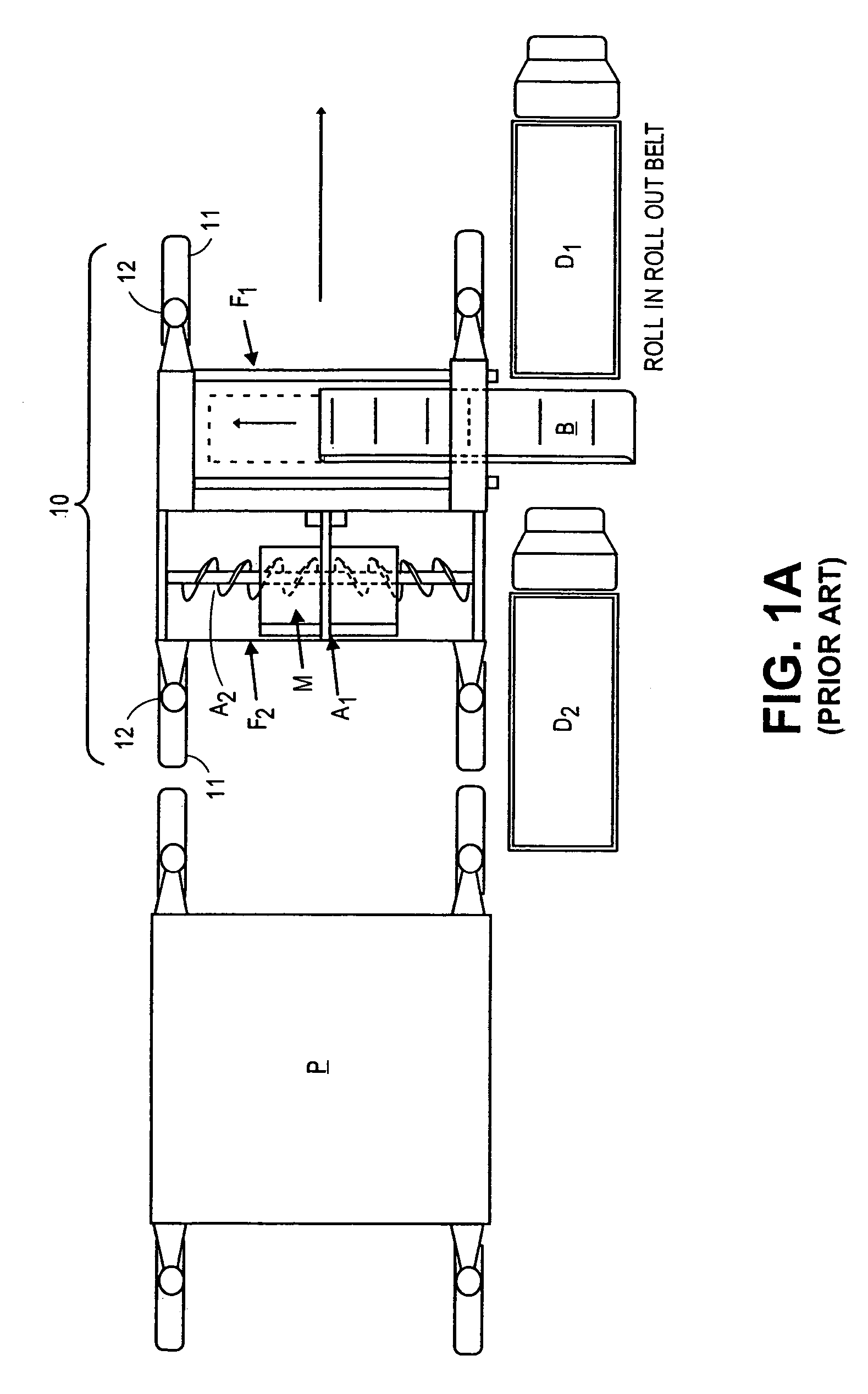
First, such roll in / roll out conveyors and their supporting structures require heavy-duty construction. When loaded with already mixed concrete their weight increases considerably. Typically, when the conveyor is rolled, it can be holding up to four yards of concrete weighing approximately 3000 pounds each. Thus the supported roll in / roll out conveyors are a heavy dynamic load, placing high load demands on their supporting frames.
This machine had superior function and productivity but was bulky, requiring multiple loads to be transported between job sites.
Further, both assembly and disassembly of the unit require a crane assist.
Disassembly and assembly of the placer / spreader was and is very time-consuming and takes days to set up and tear down.
Finally, and assuming that more concrete is placed on one side of the auger support bearing than on the other side of the auger support bearing, redistributing concrete across the central support bearing of the spreader auger is problematic at best.
Spreader augers are very costly to operate because the auger flighting and the bearings wear out rapidly when conveying abrasive concrete.
This resistance was a direct result of the extraordinarily difficult and time-consuming set-up, transport and width change costs of prior art machines utilizing roll in / roll out conveyors.

Method used


Image

  • Concrete placer/spreader having roll in/roll out conveyor
  • Concrete placer/spreader having roll in/roll out conveyor
  • Concrete placer/spreader having roll in/roll out conveyor

Examples


Embodiment Construction

[0040]Referring to FIG. 1A, the apparatus of the closest prior art is illustrated deployed for paving. Placer / spreader 10 is illustrated with frame F1 containing a telescoping conveyor belt B. Frame F2 supports machinery module M, opposed augers A1 and A2, and a central auger bearing R. As has been emphasized, the opposed augers are heavy, have relatively high power requirements for operation, and have difficulty in spreading concrete across their bearing R. The illustrated placer / spreader 10 is followed by a paver P for the forming of the placed concrete. Four crawlers 11 with attached columns 12 propel placer / spreader 10.

[0041]In operational order, the belt places the concrete, the augers spread the concrete, and finally paver P forms the concrete into the road profile. Thus the progress of the placer / spreader 10 is from the left to the right of FIG. 1A.

[0042]Concrete is typically mixed at a batch plant (not shown) and transported in dump trucks D1 and D2. In the view here shown, ...


PUM


Abstract

A placer / spreader for distributing already mixed concrete from an access road to a subgrade path to be paved includes a frame having at least two side bolsters standing parallel to the subgrade path and at least two cross beams spanning the subgrade path for forming a conveyor supporting structure. A roll in / roll out conveyor has a receiving end for receiving already mixed concrete from an access road and a discharge end for discharging already mixed concrete to the subgrade path, this conveyor being hinged to enable conformation to differing access road elevations. One of the two side bolsters defines forward and rear transport attachment points with a spatial interval between the transport attachment points. This spatial interval permits the roll in / roll out conveyor to be supported between forward and rear attachment points.

Description

BACKGROUND OF THE INVENTION[0001]This invention relates to a placer / spreader for receiving mixed concrete or base materials and distributing these materials in windrows on subgrade in the path of a slipform paver. More particularly, a placer / spreader spanning a road subgrade is provided with a roll in / roll out conveyor for receiving concrete or base material from an access road alongside the road subgrade and thereafter distributing the concrete onto the road subgrade for slipforming by a following paver. The placer / spreader includes a power unit offset from the roll in / roll out conveyor, and a beam reinforced with the conveyor track for strengthening the placer / spreader frame and supporting crawler tracks. With the roll in / roll out conveyor telescoped within and underneath the frame, the placer / spreader frame folds into a compact simplified transport configuration for shipping on a single trailer between job sites with reduced set-up time and overhead.[0002]Slipform pavers are comm...

Claims


Application Information

Patent Timeline
Patent Type & Authority Patents(United States)
IPC IPC(8): E01C19/20E01C19/12
CPCE01C19/185E01C2301/18
Inventor GUNTERT, JR., RONALD M.FRANCIS, RICK
Owner GUNTERT & ZIMMERMAN CONSTR DIV
Why Eureka
Try Eureka