Control method and apparatus for a continuously variable transmission

a technology of transmission and control method, which is applied in the direction of mechanical actuated clutches, electric propulsion mountings, hybrid vehicles, etc., can solve the problems of inability to obtain sufficient acceleration performance, increase the dimensions or weight of the mechanism, and new technical problems, so as to prevent wasteful electric power consumption, accurate detection, and small power consumption

Inactive Publication Date: 2008-01-08
HONDA MOTOR CO LTD
View PDF6 Cites 41 Cited by
  • Summary
  • Abstract
  • Description
  • Claims
  • Application Information

AI Technical Summary

Benefits of technology

[0010]To achieve the foregoing object, the present invention provides a control apparatus for a continuously variable transmission mechanism having a belt-type continuously variable transmission, an input shaft thereof being connected to a crankshaft of an engine through a staffing clutch and an output shaft thereof being connected to a driving shaft, the starting clutch being connected when a speed of the crankshaft exceeds a predetermined value, thus allowing power of the engine to be transmitted to the driving shaft through the continuously variable transmission.

Problems solved by technology

This results in a need for increasing the capacity of the transmission's starting clutch, leading to an increase in the dimensions or weight of the mechanism.
In such a case, a new technical problem arises.
Specifically, sufficient acceleration performance cannot be obtained, since the gear ratio of the continuously variable transmission is not in the low speed side when the vehicle is restarted.
There is, however, a technical problem that needs to be addressed.
As a result, a good acceleration performance cannot be obtained.

Method used


Image

  • Control method and apparatus for a continuously variable transmission
  • Control method and apparatus for a continuously variable transmission
  • Control method and apparatus for a continuously variable transmission

Examples


Embodiment Construction

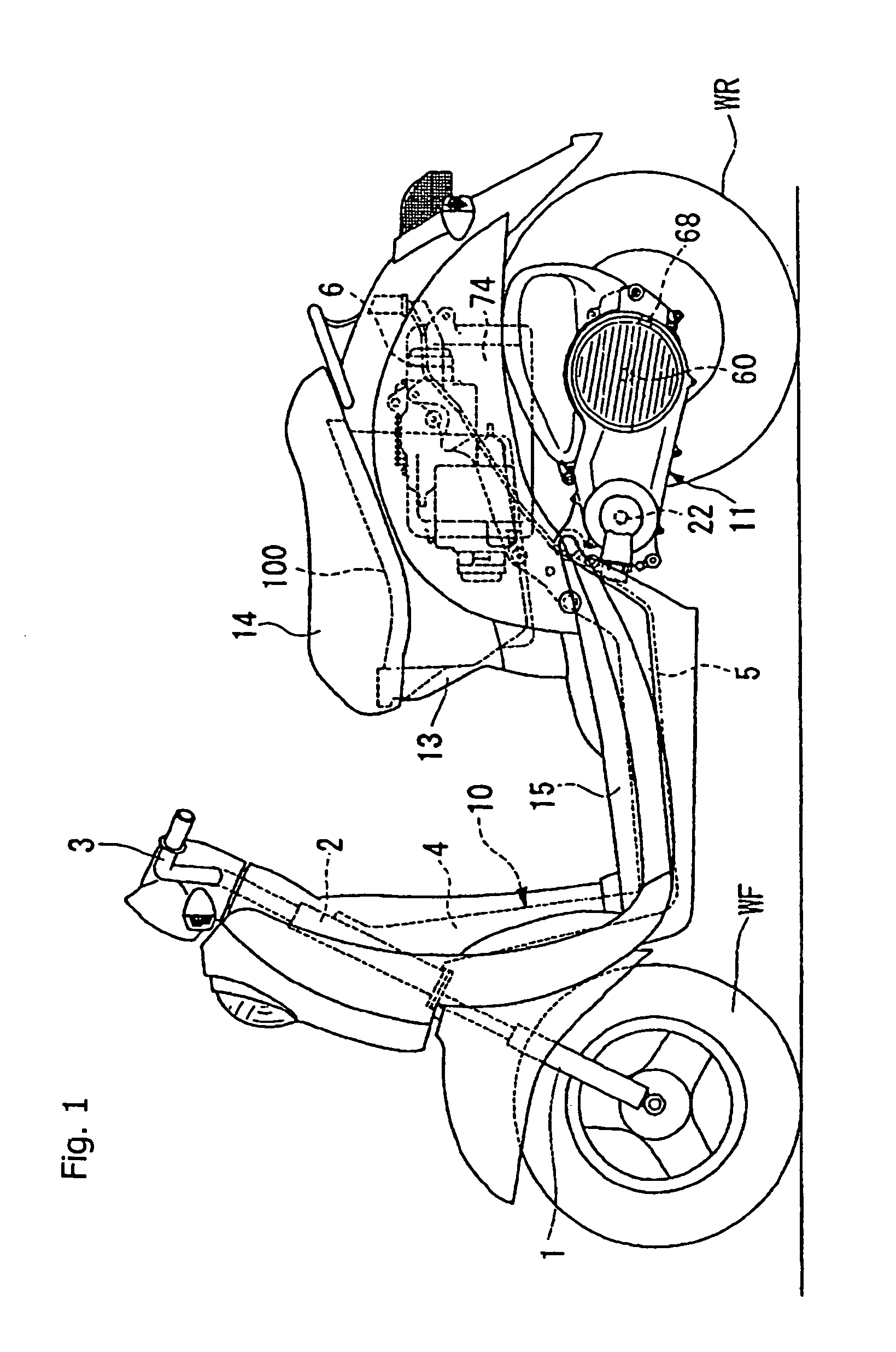
[0034]A selected illustrative embodiment of the present invention will now be described in detail, with reference to the accompanying drawings. FIG. 1 shows a hybrid vehicle according to an embodiment of the present invention. The hybrid vehicle of FIG. 1 is provided with an automatic engine stop function that brings the engine to an automatic stop when a brake is operated during running. The automatic engine stop function is provided for improved specific fuel consumption. Throughout the present specification and in the claims, an engine that has stopped running pursuant to the “automatic engine stop” function referred to above, will be referred to as being in a “stationary” state, whether or not the vehicle is moving or stationary.

[0035]The hybrid vehicle includes a front fork 1 for rotatably supporting a front wheel WF at a point forward of a vehicle body. The front fork 1 is pivotally supported on a head pipe 2. The front fork 1 can be steered through operation of a handlebar 3....


PUM


Abstract

A control apparatus for a continuously variable transmission ensures good acceleration performance during staffing operations, and following an engine stall occurring before a gear ratio of the continuously variable transmission is shifted back to a low speed. The control apparatus includes sensors, a gear ratio return control unit, and a one-way clutch. One sensor detects a gear ratio of a continuously variable transmission. Another sensor detects whether an engine is in a stationary state. The gear ratio return control unit drives a motor in a backward direction when the engine is in the stationary state and the gear ratio of the continuously variable transmission is other than a low gear ratio. The one-way clutch turns idly relative to a backward drive of the output shaft. The gear ratio return control unit brings the motor to a stop when the gear ratio of the continuously variable transmission lowers sufficiently.

Description

CROSS-REFERENCE TO RELATED APPLICATIONS[0001]The present invention claims priority under 35 USC 119 based on Japanese patent application Ser. No. 2004-232176, filed on Aug. 9, 2004. The subject matter of this priority document is incorporated by reference herein.BACKGROUND OF THE INVENTION[0002]1. Field of the Invention[0003]The present invention relates to a control method and apparatus for a continuously variable transmission. More specifically, the present invention relates to a control method and apparatus adapted to be used with a belt-type continuously variable transmission.[0004]2. Description of the Background Art[0005]Many types of transmissions are known for transmitting power from an engine to a driving wheel of a vehicle. One example of a known belt-type continuously variable transmission, for transmitting an engine driving force to a driving wheel, includes a centrifugal starting clutch provided on an output shaft (a driven side). In such an arrangement, an input of tor...

Claims


Application Information

Patent Timeline
Patent Type & Authority Patents(United States)
IPC IPC(8): B60K1/02
CPCF16H61/66259F16H2059/746F16H2061/6605Y10T477/6237Y10T477/23Y10T477/753F16H61/66
Inventor TSUKADA, YOSHIAKIOZEKI, TAKASHIKUROKI, MASAHIRO
Owner HONDA MOTOR CO LTD
Why Eureka
Try Eureka