Tensioning device, system, and method for treating mitral valve regurgitation

a technology of mitral valve and ejection tube, applied in the field of medical devices, can solve the problems of distorting the shape of the mitral valve, and reducing the ejection volume of the left ventricl

Active Publication Date: 2008-01-08
MEDTRONIC VASCULAR INC
View PDF62 Cites 558 Cited by
  • Summary
  • Abstract
  • Description
  • Claims
  • Application Information

AI Technical Summary

Problems solved by technology

This results in reduced ejection volume from the left ventricle, causing the left ventricle to compensate with a larger stroke volume.
The increased workload eventually results in dilation and hypertrophy of the left ventricle, further enlarging and distorting the shape of the mitral valve.
If left untreated, the condition may result in cardiac insufficiency, ventricular failure, and death.
This is a complex, invasive surgical procedure with the potential for many complications and a long recovery period.
Rigid annuloplasty rings have the disadvantage of causing the mitral valve annulus to be rigid and unable to flex in response to the contractions of the ventricle, thus inhibiting the normal movement of the mitral valve that is required for it to function optimally.
This eventually leads to scar tissue formation and loss of flexibility and function of the mitral valve.
Similarly, combination rings must generally be sutured in place and also cause scar tissue formation and loss of mitral valve flexibility and function.
However, the coronary sinus in a particular individual may not wrap around the heart far enough to allow effective encircling of the mitral valve, making this treatment ineffective.
While likely to be effective for modest changes in the size or shape of the mitral annulus, this device may cause significant tissue compression in patients requiring a larger change in the configuration of the mitral annulus.
Due to the nature of the anchors, both of these devices may cause significant damage to the coronary sinus and surrounding cardiac tissue.
Also, leaving a device in the coronary sinus may result in formation and breaking off of a thrombus that may pass into the right atrium, right ventricle, and ultimately the lungs, causing a pulmonary embolism.
Another disadvantage is that the coronary sinus is typically used for placement of a pacing lead, which may be precluded with the placement of the prosthesis in the coronary sinus.
However, the endovascular delivery technique is complicated, involving multiple delivery steps and devices, and requiring that special care be taken to avoid damage to the pericardium and lungs.
Excess length of the tension member is thermally severed prior to removal, again posing some risk to tissue in and around the heart.

Method used


Image

  • Tensioning device, system, and method for treating mitral valve regurgitation
  • Tensioning device, system, and method for treating mitral valve regurgitation
  • Tensioning device, system, and method for treating mitral valve regurgitation

Examples


Embodiment Construction

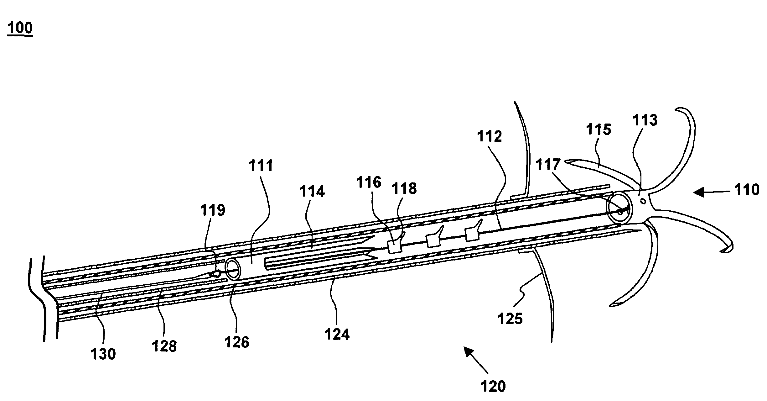
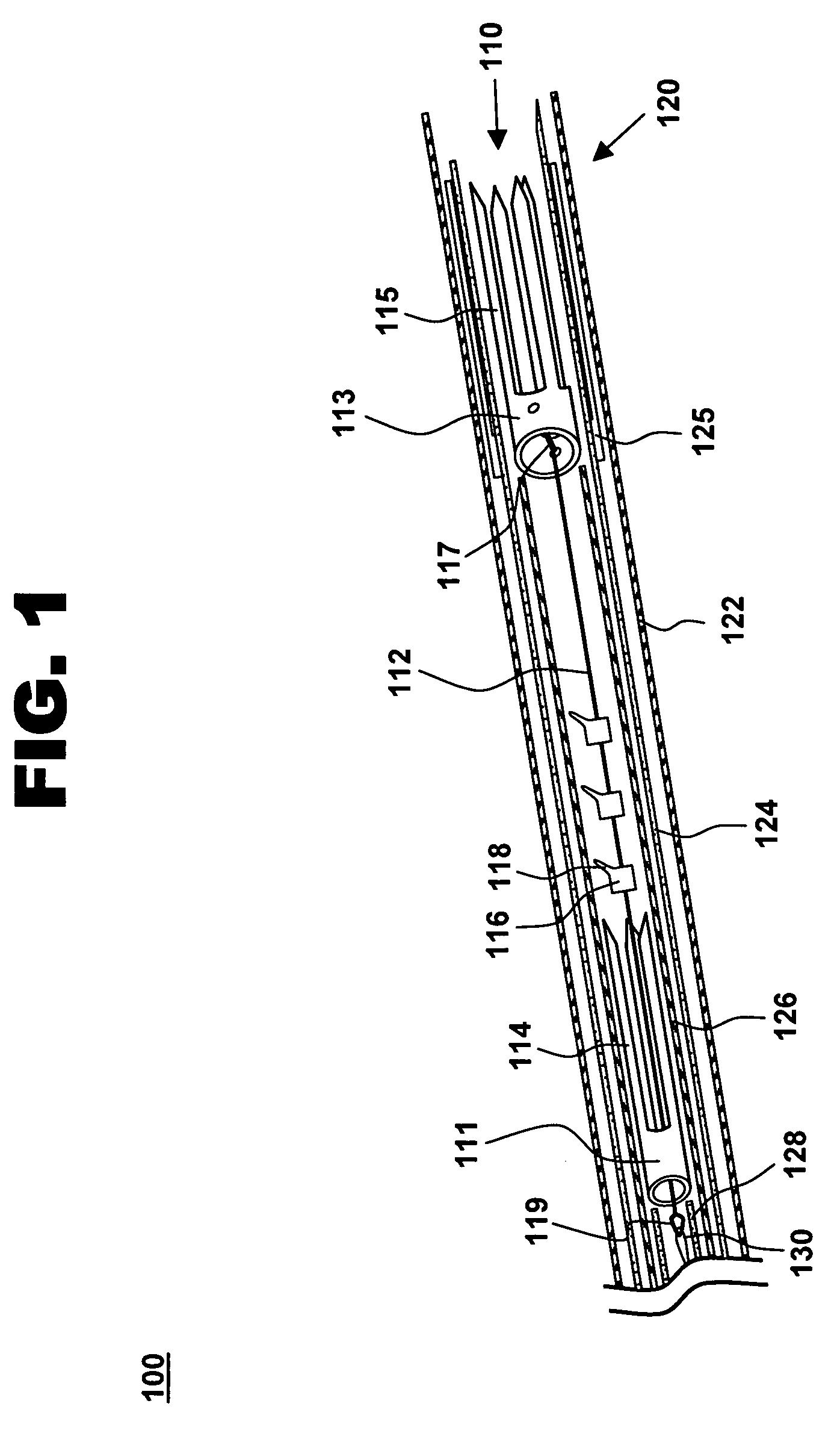
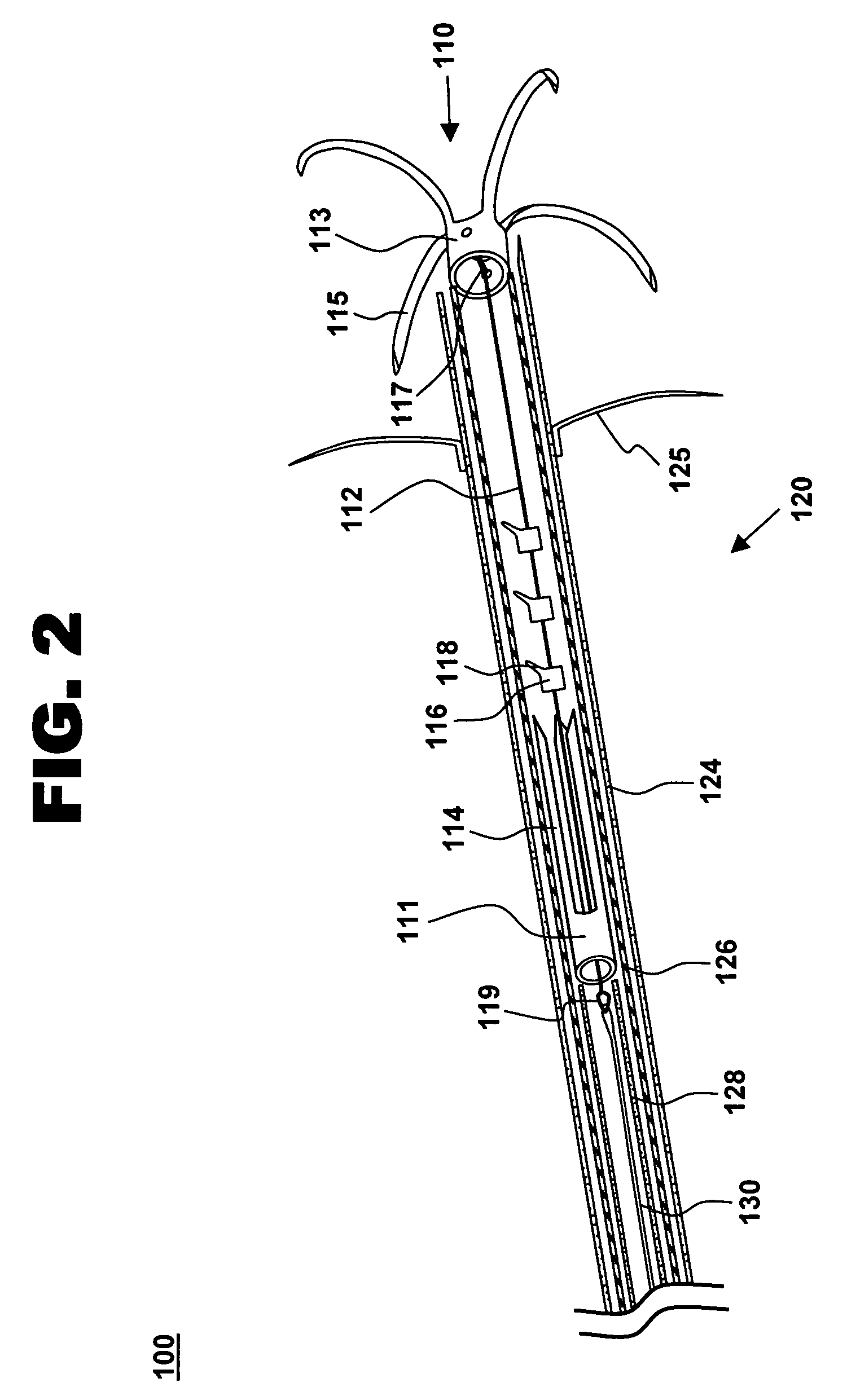
[0027]One aspect of the present invention is a tensioning device for treating mitral valve regurgitation. One embodiment of the device, in accordance with the present invention, is illustrated in FIGS. 1-3 at 110.

[0028]Tensioning device 110 is designed to be positioned across a chamber of a heart using minimally invasive catheterization techniques. Although described below in the context of treating mitral valve regurgitation by reducing or limiting lateral distension of the left ventricle as the heart beats, device 110 may be deployed at other locations in the heart and is readily adapted to a wide variety of uses, including treating ischemic or dilated cardiomyopathy.

[0029]Tensioning device 110 includes proximal anchoring member 111 positioned adjacent to the proximal end of tether 112, and distal anchoring member 113 positioned adjacent to the distal end of tether 112. As used herein, the terms “distal” and “proximal” are with reference to the treating clinician during deployment...


PUM


Abstract

A system for treating mitral valve regurgitation comprises a tensioning device slidably received within a delivery catheter. The tensioning device includes a tether linking proximal an anchoring member and a distal anchoring member. At least one of the anchoring members includes an elastic portion that flexes in response to a heartbeat when the tensioning device is positioned across a chamber of a heart. The tether includes at least one locking member initially positioned between the anchoring members. A method for treating mitral valve regurgitation comprises piercing a first wall of a chamber of a heart, engaging a distal anchoring member with a second wall of the heart chamber, engaging a proximal anchoring member with the first wall, and pulling a locking member affixed to a tether linking the anchoring members from an initial position between the two anchoring members to a locked position proximal the proximal anchoring member.

Description

PRIORITY CLAIM[0001]This application claims the benefit of U.S. Provisional Application No. 60 / 480,195 filed Jun. 20, 2003; U.S. Provisional Application No. 60 / 480,472 filed Jun. 20, 2003; and U.S. Provisional Application No. 60 / 503,035 filed Sep. 15, 2003; the entirety of each of which is hereby incorporated by reference.TECHNICAL FIELD[0002]This invention relates generally to medical devices and particularly to a system and method for treating mitral valve regurgitation.BACKGROUND OF THE INVENTION[0003]The heart is a four-chambered pump that moves blood efficiently through the vascular system. Blood enters the heart through the vena cava and flows into the right atrium. From the right atrium, blood flows through the tricuspid valve and into the right ventricle, which then contracts and forces blood through the pulmonic valve and into the lungs. Oxygenated blood returns from the lungs and enters the heart through the left atrium and passes through the bicuspid mitral valve into the...

Claims


Application Information

Patent Timeline
Patent Type & Authority Patents(United States)
IPC IPC(8): A61B17/04A61B17/08A61F2/00A61F2/24
CPCA61F2/2487A61B2017/00243A61B2017/00783A61B2017/0409A61B2017/0437A61B2017/0445A61B2017/0462A61B2017/0464
Inventor BLOOM, ELIOTDOUK, NAREAKHORRIGAN, JOHNHUYNH, RANYRAFIEE, NASSER
Owner MEDTRONIC VASCULAR INC
Why Eureka
Try Eureka