Optical film, light reflective film, liquid crystal display panel, method and apparatus for producing an optical film, method of producing a die roller, and method and apparatus for laminating an optical film

Inactive Publication Date: 2008-01-08
SHARP KK
View PDF19 Cites 19 Cited by
  • Summary
  • Abstract
  • Description
  • Claims
  • Application Information

AI Technical Summary

Benefits of technology

[0013]It is a first object of the invention to provide an optical film and a light reflective film which can be easily lamin

Problems solved by technology

The irregular concave and convex portions in JP-A 2000-47199 cause a problem in that the directivity of reflected light is lowered.
In a liquid crystal display panel, particularly,

Method used


Image

  • Optical film, light reflective film, liquid crystal display panel, method and apparatus for producing an optical film, method of producing a die roller, and method and apparatus for laminating an optical film
  • Optical film, light reflective film, liquid crystal display panel, method and apparatus for producing an optical film, method of producing a die roller, and method and apparatus for laminating an optical film
  • Optical film, light reflective film, liquid crystal display panel, method and apparatus for producing an optical film, method of producing a die roller, and method and apparatus for laminating an optical film

Examples


Embodiment Construction

[0078]Now referring to the drawings, preferred embodiments of the invention are described below.

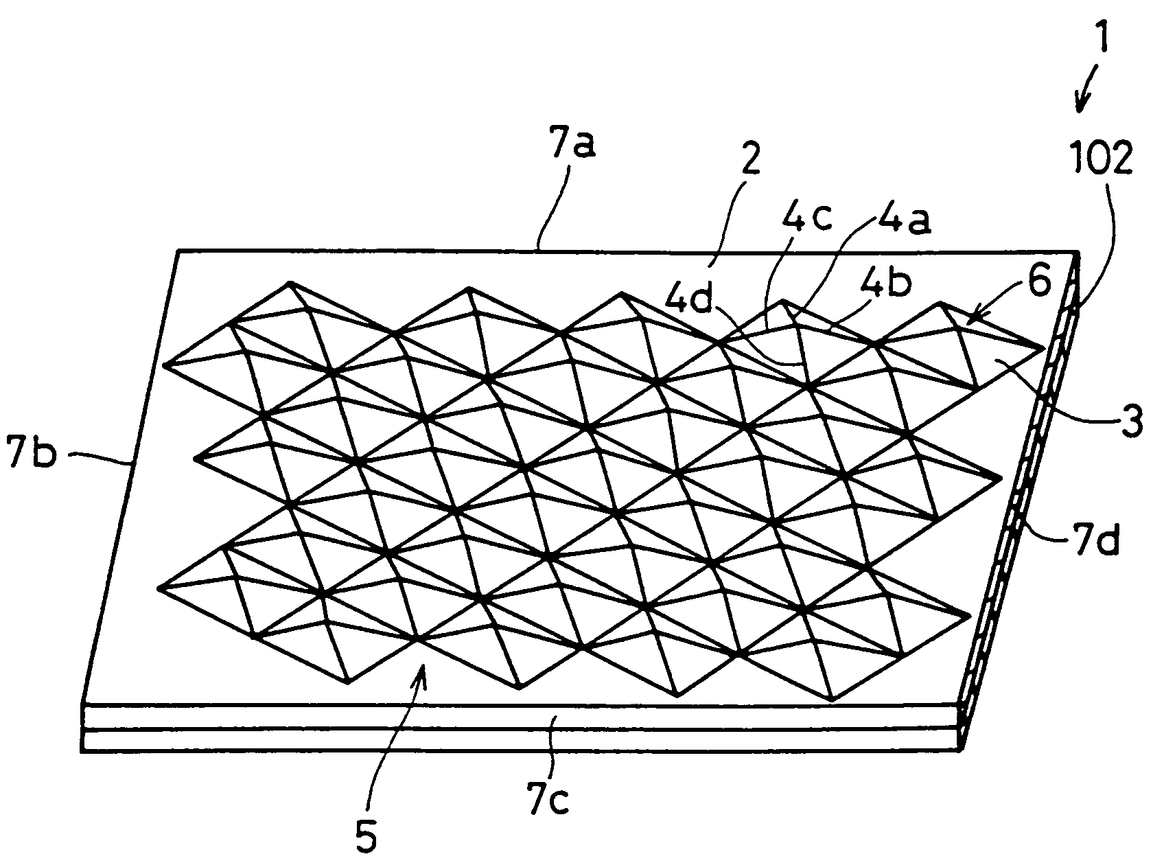
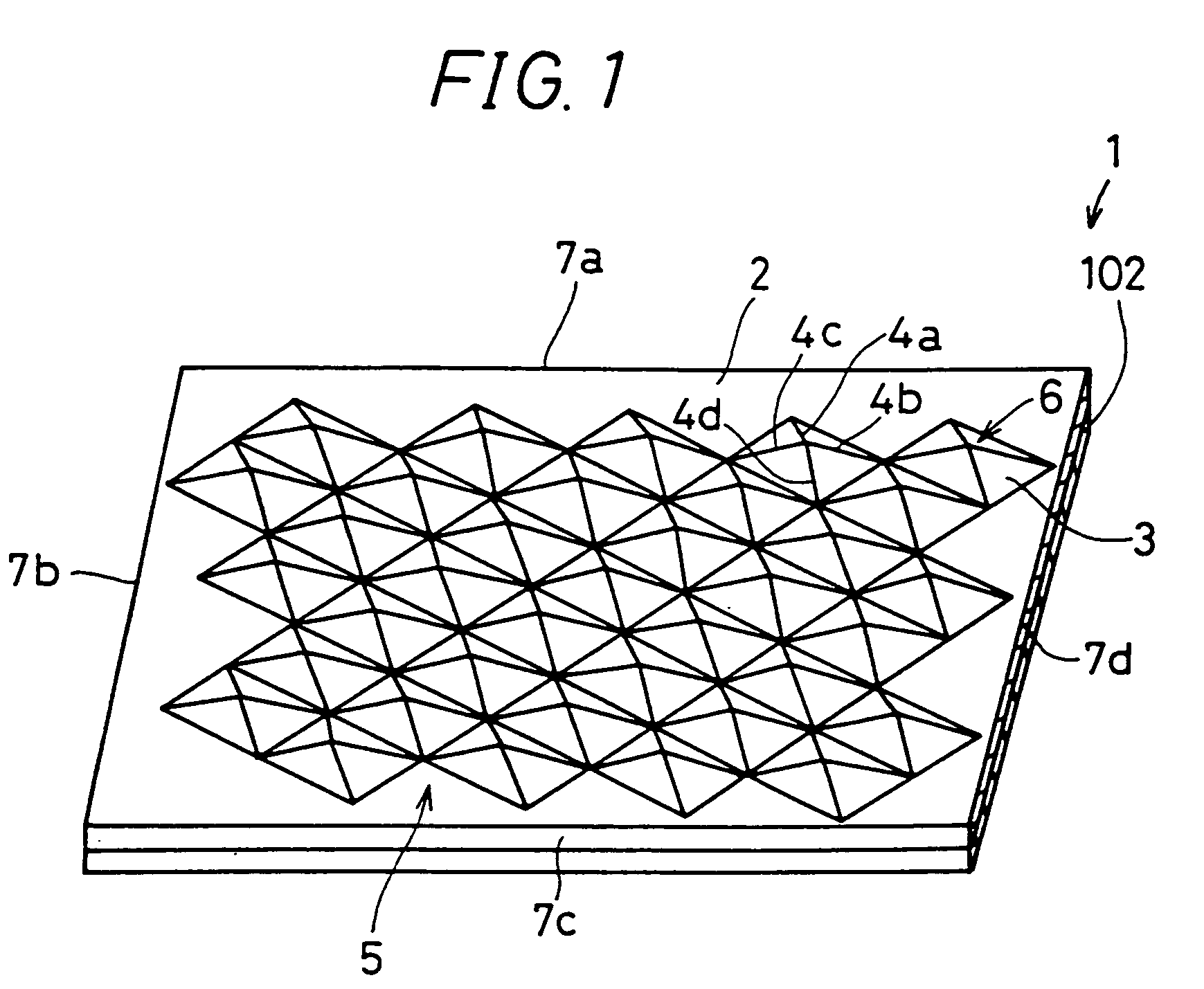
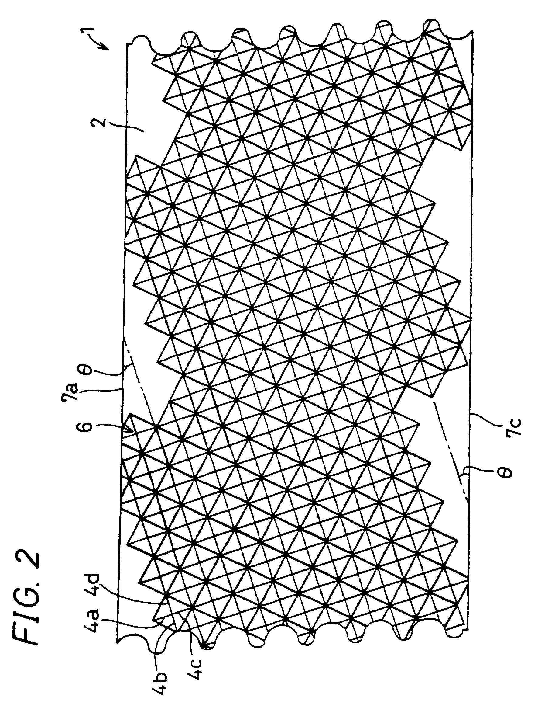
[0079]FIG. 1 is a perspective view showing a die film 1 of an embodiment of the invention, FIG. 2 is a plan view of the die film 1 shown in FIG. 1, and FIG. 3 is a view showing a die film 1a of another embodiment of the invention. When the die films 1 and 1a are to be generally referred, they are called merely the die film 1. The die film 1 is configured by a resin base material 2 and a base film 102. A rough face 5 in which a plurality of pyramidal convex portions 3 are regularly arranged is formed in one surface of the resin base material 2 having a strip-like and film-like shape. The base film 102 is laminated to the other surface of the base resin material 2.

[0080]For example, each of the convex portions 3 is a quadrangular pyramid having a square bottom face in which the length of one side is 40 μm, and a height of 2 μm. The plural convex portions 3 are linearly continuously formed t...


PUM

PropertyMeasurementUnit
Angleaaaaaaaaaa
Angleaaaaaaaaaa
Angleaaaaaaaaaa

Abstract

An object of the invention is to provide a light reflective film which can prevent moire fringes from occurring. A rough face in which a plurality of rows of pyramidal convex portions that are linearly continuous are adjacently formed in parallel with one another is formed on one face of a die film. The rows of convex portions that are linearly continuous are inclined at a predetermined angle with respect to an edge of the die film. An optical film is produced by transferring the die film. A light reflective film is produced by vapor-depositing a light reflection film on the optical film. In a liquid crystal display panel having the light reflective film, the pitch of occurring moire fringes becomes so small that the moire fringes cannot be visually seen, and moire fringes can be prevented from occurring.

Description

BACKGROUND OF THE INVENTION[0001]1. Field of the Invention[0002]The present invention relates to an optical film, a light reflective film, a liquid crystal display panel, a method and apparatus for producing an optical film, a method of producing a die roller, and a method and apparatus for laminating an optical film.[0003]2. Description of the Related Art[0004]Recently, application of a liquid crystal display panel to a word processor, a laptop personal computer, a pocket television, a portable telephone, and the like is rapidly advancing. Among liquid crystal display panels, a reflection type liquid crystal display panel and a semi-transmission type liquid crystal display panel in which light entering from the outside is reflected by a light reflective film receive attention because external light can be used so as to attain a lower power consumption, and the thickness and weight of the panel can be reduced.[0005]In the field of a portable telephone and the like, a request for a m...

Claims


Application Information

Patent Timeline
IPC IPC(8): G02F1/133B31F1/20B32B3/00G02B5/02B29C59/04G02B5/08G02F1/1335
CPCG02B5/08G02F1/133553Y10T428/24612
Inventor TANAKA, MITSUHIROSAAI, YUJI
Owner SHARP KK
Why Eureka
Try Eureka