Parallel current mode control using a direct duty cycle algorithm with low computational requirements to perform power factor correction

a technology of parallel current mode and power factor correction, applied in the direction of electric variable regulation, process and machine control, instruments, etc., can solve the problems of not being optimized for digital implementation, conventional analog control methods cannot meet the requirements of power factor correction, and becoming more and more complicated

Inactive Publication Date: 2008-01-08
DIALOG SEMICONDUCTOR INC
View PDF41 Cites 43 Cited by
  • Summary
  • Abstract
  • Description
  • Claims
  • Application Information

AI Technical Summary

Benefits of technology

[0009]Another object of the present invention is to provide a method that is optimized for digital implementation to achieve unity power factor for AC-DC converter. The proposed PFC control method can be implemented by a low cost DSP, FPGA or ASIC due to its low computation requirement. It overcomes the disadvantages of the existing digital PFC techniques mentioned above, such as high computation requirement, model sensitivity and increased harmonics.BRIEF STATEMENT OF INVENTION

Problems solved by technology

In addition, the power requirement is becoming more and more complicated and the conventional analog control method can no longer meet this requirements.
They are not optimized for digital implementation.
Unfortunately, the conventional current mode control methods are optimized for analog implementation.
It is very difficult to implement those methods using digital circuits.
There are several disadvantages in existing digital control PFC implementation systems based on conventional current mode control, such as high computational requirement, limited switching frequency and high cost.
The first disadvantage is that the duty cycle calculation requires the duty cycle value in the previous switching cycle.
Second, the computation requirement is not obviously reduced compared to that in the digital PFC implementation based on current mode control.
However, the current waveform is sensitive to the parameters of the model and the capability of the regulation to the step load change is not satisfied when the load variation is wide.

Method used


Image

  • Parallel current mode control using a direct duty cycle algorithm with low computational requirements to perform power factor correction
  • Parallel current mode control using a direct duty cycle algorithm with low computational requirements to perform power factor correction
  • Parallel current mode control using a direct duty cycle algorithm with low computational requirements to perform power factor correction

Examples


Embodiment Construction

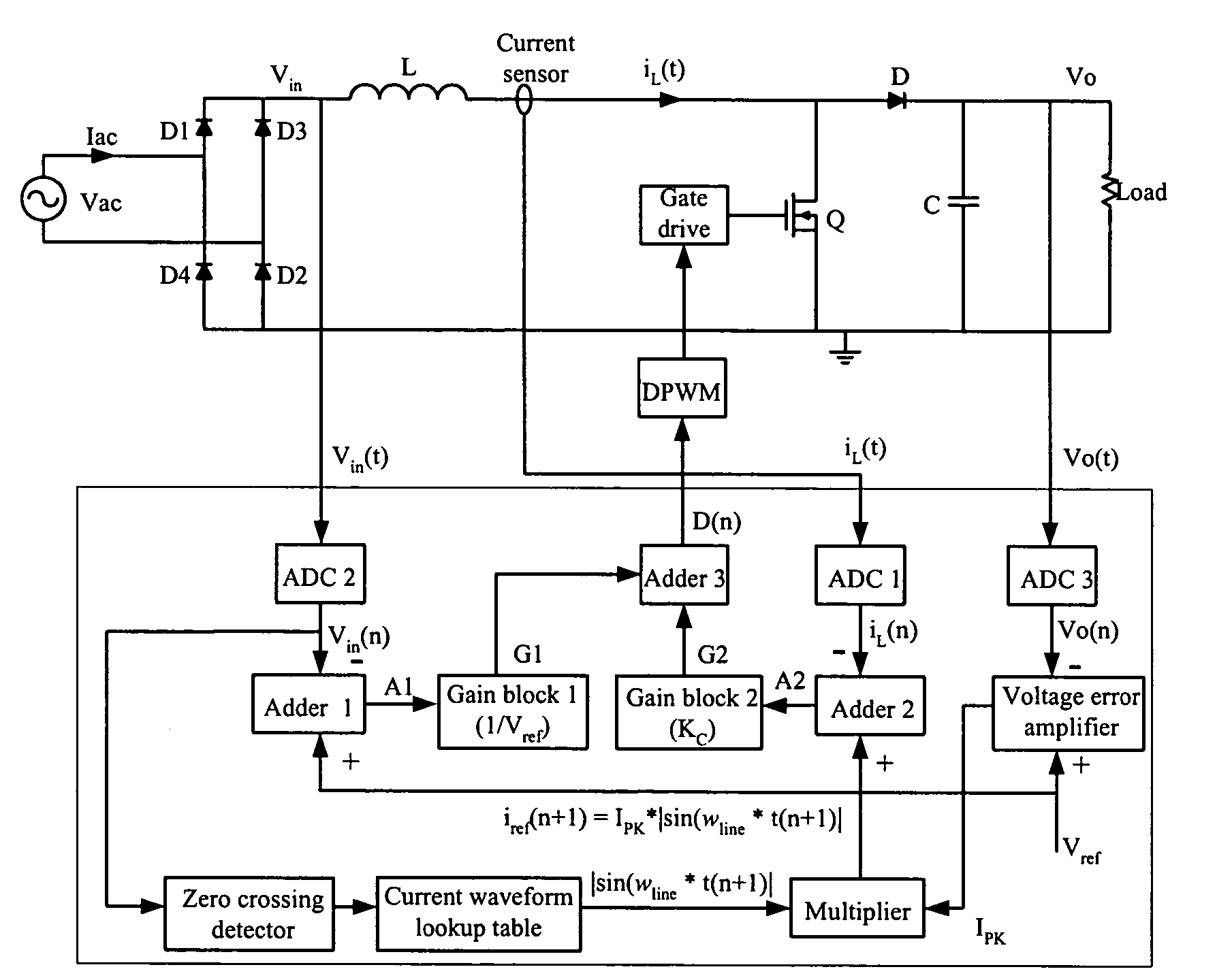
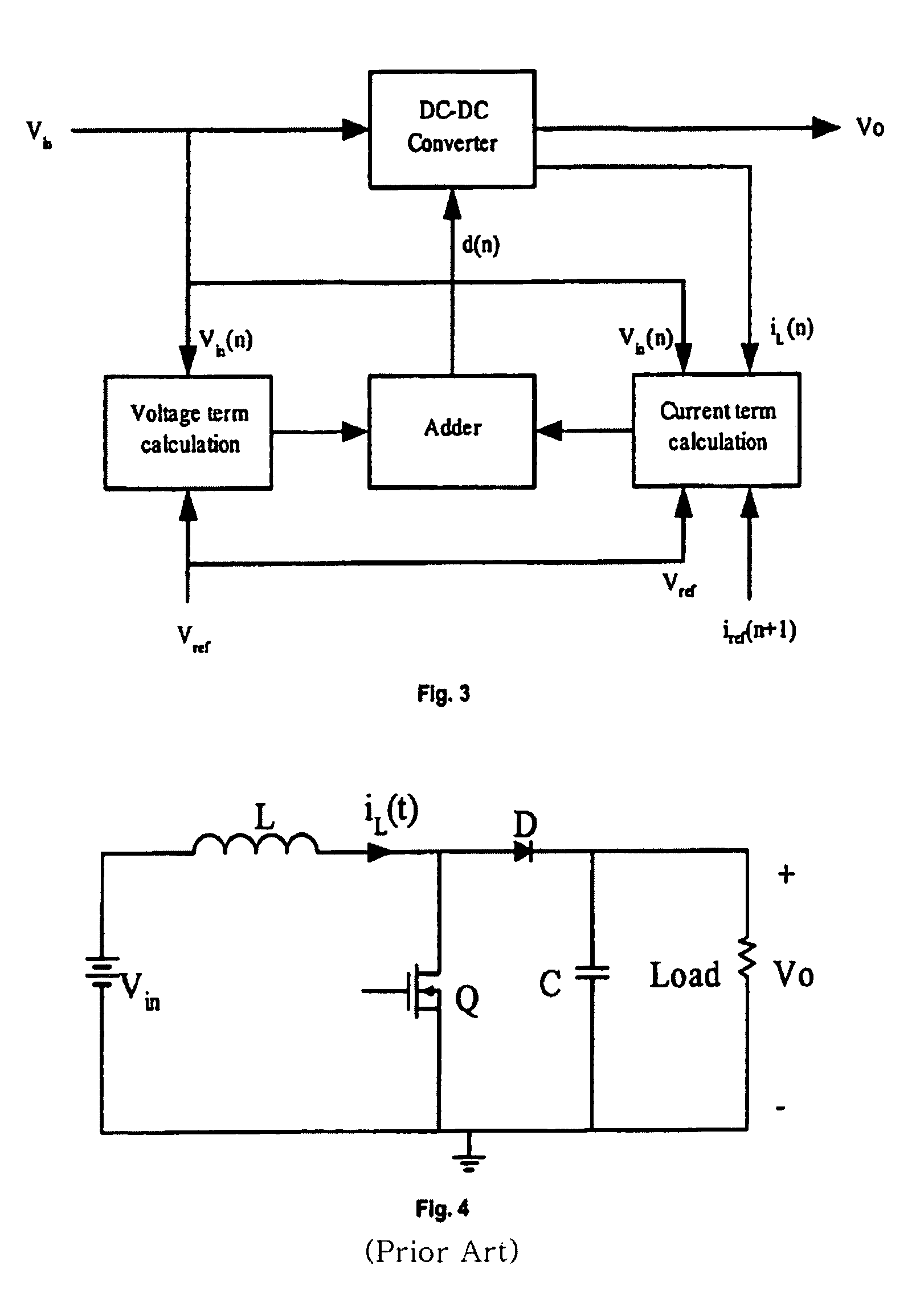
[0042]According to the present control method, the duty cycle is composed of two parallel terms. The first term is called the “voltage term”. It depends on the input voltage and the desired output voltage. The expression of this term depends on the topology of the switching converters. Essentially, this term is determined by the volt-second balance of the specific converter. The second term is called the “current term” and it depends on the inductor current change between the inductor current value at the beginning of the switching cycle and the reference inductor current value at the end of that switching cycle. With this parallel current mode control method, the inductor current of the converter, such as Buck-Boost, Boost, Buck, etc., will follow the reference current with a difference gap between the reference current value and actual inductor current value. This difference gap is determined by the load condition. At the same time, the output voltage of the converter will exactly...


PUM


Abstract

A method and apparatus to implement parallel current mode control that is suitable for digital and analog implementation. A duty cycle algorithm is composed of a voltage term and a parallel current term which depends on the inductor current change between the inductor current value at the beginning of a switching cycle and the reference inductor current value at the end of that switching cycle. Parallel current mode control can be applied to all DC-DC converters, including both non-isolated and isolated topologies. It can also be applied to AC-DC converters with power factor correction.

Description

FIELD OF INVENTION[0001]This invention relates to electronic power supply converters for energy systems and more particularly to DC-DC converter and AC-DC converter with power factor correction.BACKGROUND OF INVENTION AND PRIOR ART[0002]Digital control is becoming more and more popular because of the process advancement of CMOS technology. In addition, the power requirement is becoming more and more complicated and the conventional analog control method can no longer meet this requirements. Digital control of power converter and power system can meet these more and more complicated power requirement. It is expected that digital control will replace analog control in switching power converters.[0003]At the present time, the control algorithms used in digital controllers are translated directly from analog algorithms. In other words, they are digital implementation of the algorithms that are optimized for analog implementation. They are not optimized for digital implementation.[0004]F...

Claims


Application Information

Patent Timeline
Patent Type & Authority Patents(United States)
IPC IPC(8): H02M5/42G05F1/00G05F1/70H02M1/42H02M3/157H02M3/335
CPCH02M1/4225H02M3/157H02M2001/4275Y02B70/126Y02B70/10Y02P80/10H02M1/4275
Inventor ZHANG, WANFENGLIU, YAN-FEIWU, BIN
Owner DIALOG SEMICONDUCTOR INC
Why Eureka
Try Eureka