Method of Controlling the direction of rotation of a power tool

a technology of power tools and rotation directions, applied in the field of power tools, to achieve the effect of convenient operation

Inactive Publication Date: 2008-01-15
C & E FEIN GMBH & CO KG
View PDF15 Cites 43 Cited by
  • Summary
  • Abstract
  • Description
  • Claims
  • Application Information

AI Technical Summary

Benefits of technology

[0008]It is an object of the present invention to disclose an improved power tool, in particular a screw runner or a drilling machine, which guarantees easier operation, in particular an improved reversal between clockwise / counter-clockwise rotation.

Problems solved by technology

Effecting the changeover mechanically presents, however, a disadvantage when the screw runner is to be operated in opposite direction, i.e. the direction opposite to the preset clockwise or counter-clockwise rotation, because in this case the changeover switch has to be actuated once more to effect clockwise or counter-clockwise rotation.

Method used


Image

  • Method of Controlling the direction of rotation of a power tool
  • Method of Controlling the direction of rotation of a power tool
  • Method of Controlling the direction of rotation of a power tool

Examples


Embodiment Construction

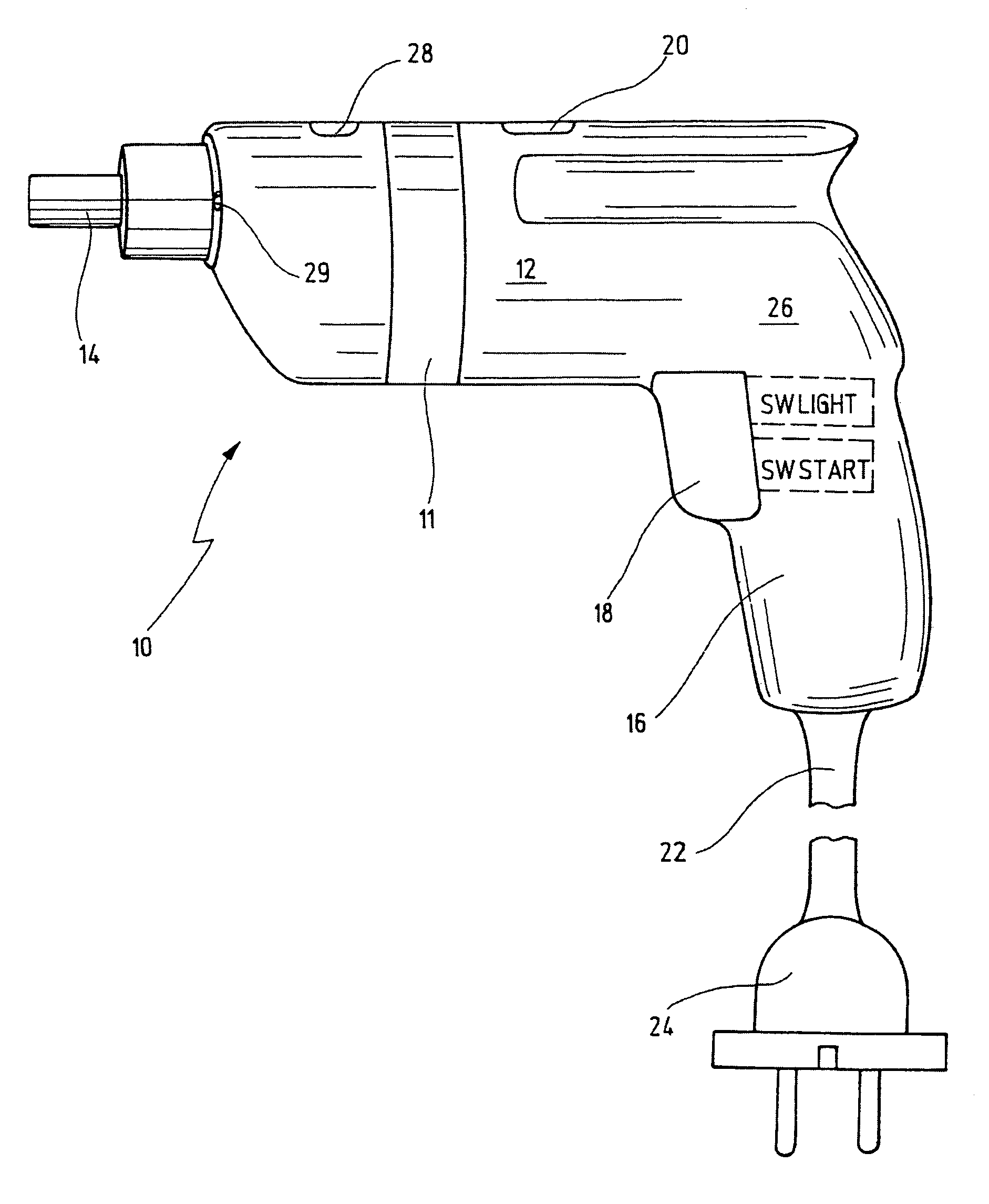
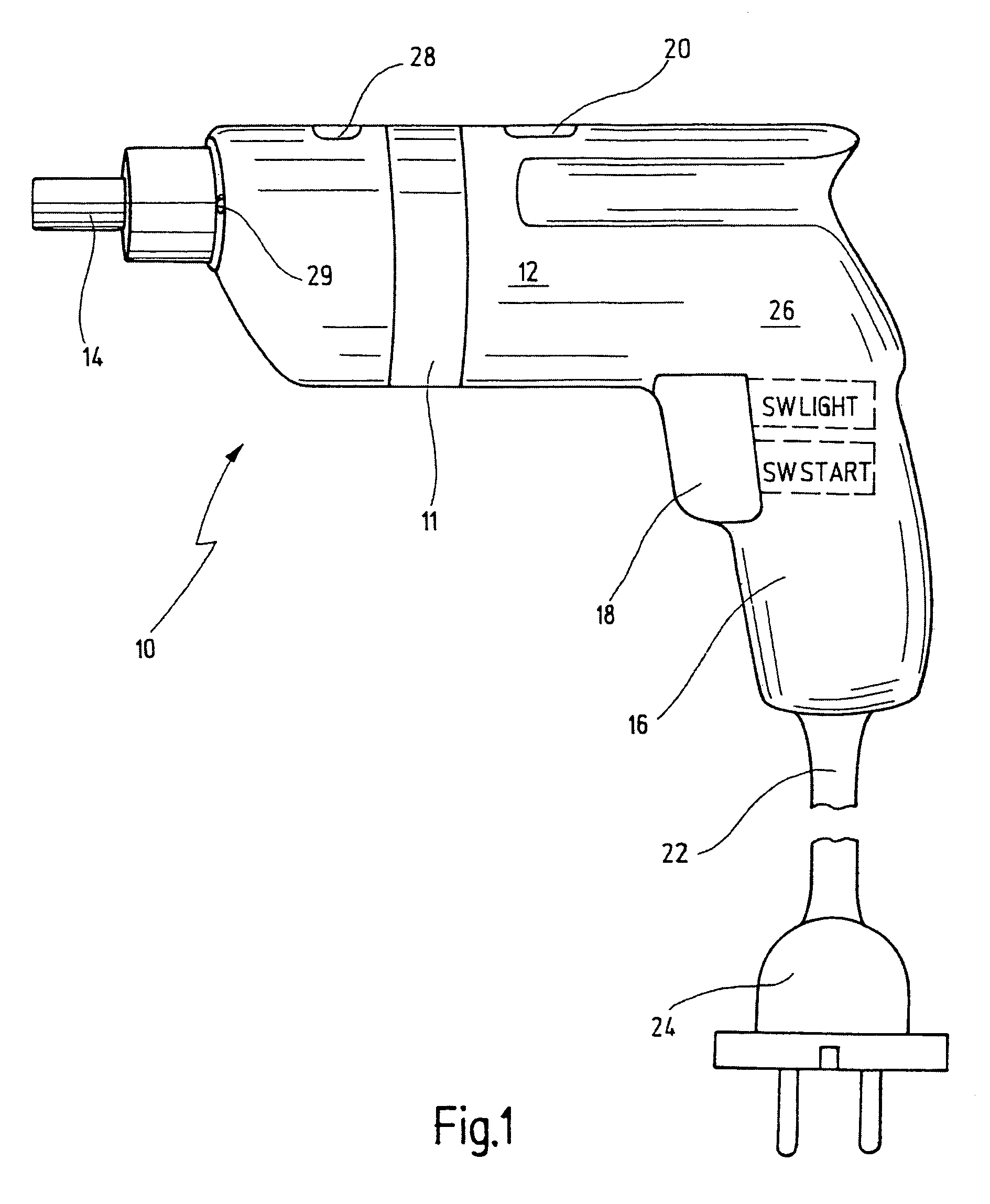
[0058]In FIG. 1, a power tool according to the invention being configured of a screw runner is shown and indicated generally by reference numeral 10.

[0059]The power tool 10 comprises a pistol-shaped housing 11 in which are received a motor, merely indicated by reference numeral 12, a gearing and a controller 26. The motor 12 drives, via a gearing not shown in detail, a drive shaft 14 intended to drive a tool, for example the bit of a screw runner. At the forward end of the housing 11, facing the drive shaft 14, there are provided a series of lighting elements 29, such as LEDs, that radiate in forward direction and allow the working position to be illuminated (in FIG. 1, a single LED can be seen only). At its lower end, the housing 11 comprises a pistol grip 16, with a line cord 22 provided on the latter's lower end for connection to a voltage source via a mains plug 24. A trigger 18 is provided in the area of the “pistol trigger” for actuation of the motor 12 and the lighting elemen...


PUM


Abstract

The invention discloses a power tool for screwing or drilling having a motor for driving a drive shaft, a controller for controlling the power tool, a motor switch for switching the motor on and off, switch for reversing the power tool between clockwise and counter-clockwise rotation, and vice versa, and a timer that permits reversal of the power tool between clockwise / counter-clockwise rotation, and vice versa, within a predefined period of time between actuation of the switch for clockwise / counter-clockwise rotation and for operation of the motor switch to start the power tool.

Description

CROSS-REFERENCE TO RELATED APPLICATIONS[0001]The present application claims priority of German patent application No. 20 2004 019 853.3 filed on Dec. 15, 2004.BACKGROUND OF THE INVENTION[0002]The present invention relates to a power tool, in particular a power tool which is configured as screw runner or a drill, the power tool having a motor for driving a drive shaft, a controller for controlling the power tool, a motor switch for switching the motor on and off, and switching means for reversing the power tool between clockwise and counter-clockwise rotation.[0003]The invention further relates to a method of controlling the direction of rotation of a power tool.[0004]Drilling machines or screw runners of that kind have been in use for a long time.[0005]Reversal between clockwise and counter-clockwise rotation is normally effected by actuation of a mechanical changeover switch.[0006]In operation, screw runners normally are operated in permanent clockwise rotation or permanent counter...

Claims


Application Information

Patent Timeline
Patent Type & Authority Patents(United States)
IPC IPC(8): B25B21/00
CPCB25B21/00
Inventor GREESE, OLIVERSCHOLL, THOMAS
Owner C & E FEIN GMBH & CO KG
Why Eureka
Try Eureka