Heat-flux based emissivity/absorptivity measurement

a technology of emissivity and absorption, applied in the field of apparatus and methods for measuring thermal emissivities, can solve the problems of inability to use emissivity measurement systems in laboratory or under special conditions, and the measurement of the amount of radiated heat is more difficult, and achieve the effect of accurate measuremen

Inactive Publication Date: 2008-01-15
ATEC INC
View PDF1 Cites 19 Cited by
  • Summary
  • Abstract
  • Description
  • Claims
  • Application Information

AI Technical Summary

Benefits of technology

[0014]a) It is an object of this invention to provide a mechanism for accurate measurement of data from which emissivity or absorptivity characteristic of a surface can be calculated.
[0015]b) It is a further object to provide such a mechanism that provides direct measurement of the heat flow to or from the emitting/absorbing surface.
[0016]c) It is a further objective of the mechanism to apply a heat-flux sensor in substantial thermal contact with the radiating/

Problems solved by technology

Measurement of the amount of radiated heat is more difficult.
This and other related information are found at: (http://www.npl.co.uk/thermal/stuff/guide4.html)

Method used


Image

  • Heat-flux based emissivity/absorptivity measurement
  • Heat-flux based emissivity/absorptivity measurement
  • Heat-flux based emissivity/absorptivity measurement

Examples


Embodiment Construction

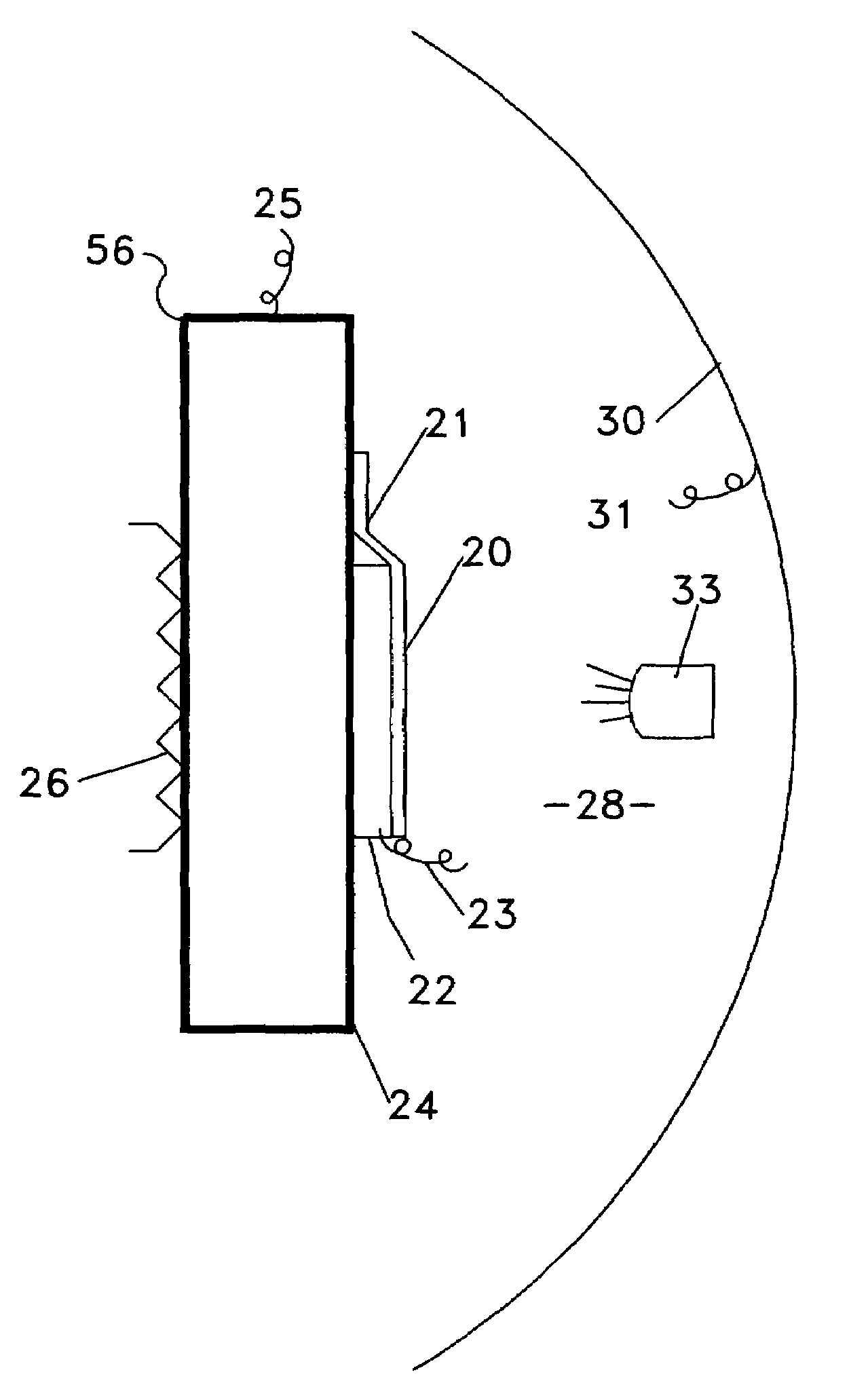
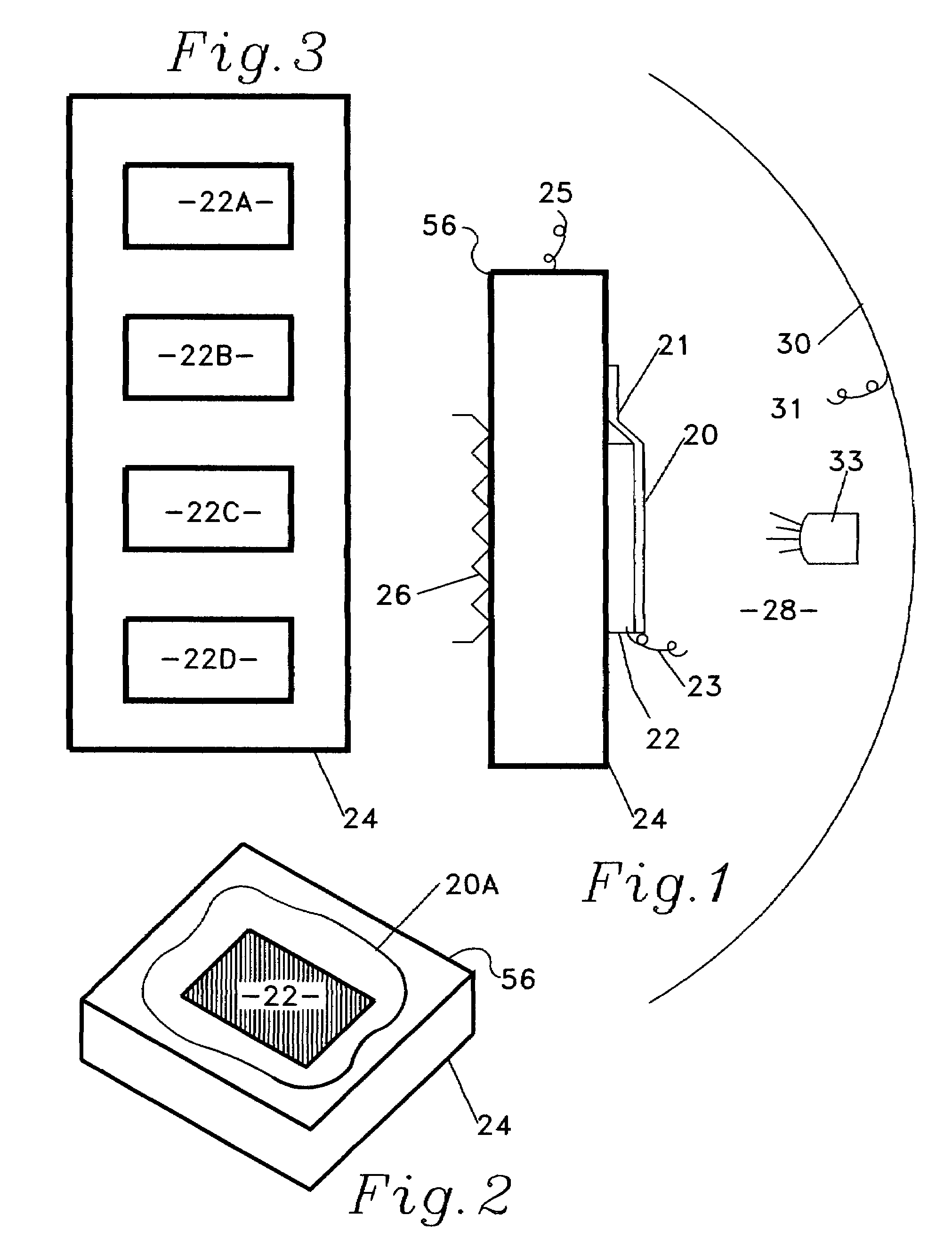
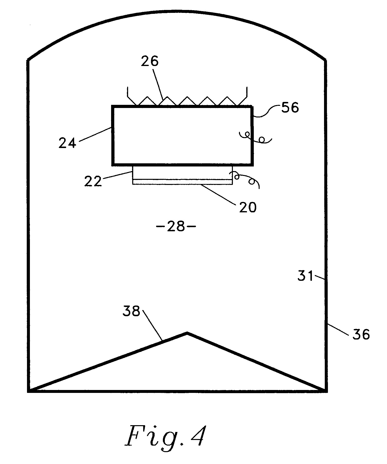
[0034]In the following description the surface 20 is substantially always described as an emitting surface. However, the heat-flux sensor can indicate and measure heat flow in either direction; 1) from the heat source 24, whose temperature is dropping, through the heat-flux sensor 22 and the emitting surface 20 to an external heat sink or, 2) in contrast, from an external source of radiant energy 33 to surface 20, now an absorbing surface, through heat-flux sensor 22 to heat sink 24 whose temperature is now rising. It must be noted that surfaces are being developed that have an externally controllable emissivity. Such a surface is described in a paper titled, “Electrostatic Switchable Applique” by Biter, Hess and Oh, (CP746 Space Technology and Applications International Forum, STAIF 2005) and is or will be used for temperature control in spacecraft. Such emissivity-controllable surfaces are called ‘Active’ surfaces. The invention disclosed herein is unusually applicable to real-tim...


PUM


Abstract

A mechanism and method for directly observing data from which the thermal emissivity or absorptivity of a surface can be calculated. The invention teaches the use of a substantially planar heat-flux or heat-flow sensor employing a thermopile, to measure the rate of heat dissipation from a radiating surface thermally attached to one side of the heat-flux sensor where the radiating surface is exposed to a first temperature and where the second side of the heat flux sensor is in thermal contact with a heat source at a second higher temperature.

Description

PRIORITY[0001]This Non-Provisional patent application claims priority based on a Provisional Patent Application filed 23 Sep. 2004 (09-23-2004) having Ser. No. 60 / 612,365 having the same inventors and substantially the same title.STATEMENT REGARDING FEDERALLY SPONSORED OR-FUNDED RESEARCH[0002]This invention was made with Government Support under Contract FA8650-04-M-5020 awarded as an Air Force SBIR Phase I Project.[0003]The Government has certain rights in the invention.BACKGROUND OF THE INVENTION[0004]1. Field of the Invention[0005]This invention relates to improved apparatus and method for measuring the thermal emissivities of surfaces and coatings.[0006]2. Background of the Art[0007]To simplify the following discussion the term heat loss and the term emissivity are used and the object or surface under discussion is considered to be at a higher temperature than its environment. However, it should be noted that an object can gain or lose heat by conduction and convection to a vapo...

Claims


Application Information

Patent Timeline
IPC IPC(8): G01N25/00
CPCG01N25/18
Inventor MOGHADDAM, SAEEDLAWLER, JOHNKIM, JUNGHO
Owner ATEC INC
Why Eureka
Try Eureka