Check patentability & draft patents in minutes with Patsnap Eureka AI!

Frame synchronization in multi-cell systems with a data interface

a multi-cell, data interface technology, applied in multiplex communication, transmission monitoring, wireless commuication services, etc., can solve the problem of waste of extra wiring b>130/b> for fs only

Inactive Publication Date: 2008-01-15
IND TECH RES INST
View PDF41 Cites 6 Cited by
  • Summary
  • Abstract
  • Description
  • Claims
  • Application Information

AI Technical Summary

Benefits of technology

The present invention is a method and apparatus for synchronizing transmission of data frames from multiple base stations in a communication system. The invention solves problems related to synchronization in existing systems. The technical effects of the invention include regular and automatic synchronization among base stations, improved signal handoff, and better performance against interference. The invention involves determining signal propagation delays to each base station, storing the delay in each base station, and delaying transmission of data frames from each base station by an amount determined from the stored delay.

Problems solved by technology

Unfortunately, because the RFPs are different distances from the CCFP, even if the CCFP transmits a synchronization signal, the signal will arrive at the RFPs at different times due to different propagation delays from the CCFP to the respective RFPs.
Using this system, the time delays for each base station may be compensated for with high accuracy, but the required extra wiring 130 for FS only is wasteful.

Method used


Image

  • Frame synchronization in multi-cell systems with a data interface
  • Frame synchronization in multi-cell systems with a data interface
  • Frame synchronization in multi-cell systems with a data interface

Examples


Embodiment Construction

[0022]Reference will now be made in detail to the present preferred embodiments of the invention, examples of which are illustrated in the accompanying drawings. Wherever possible, the same reference numbers will be used throughout the drawings to refer to the same or like parts.

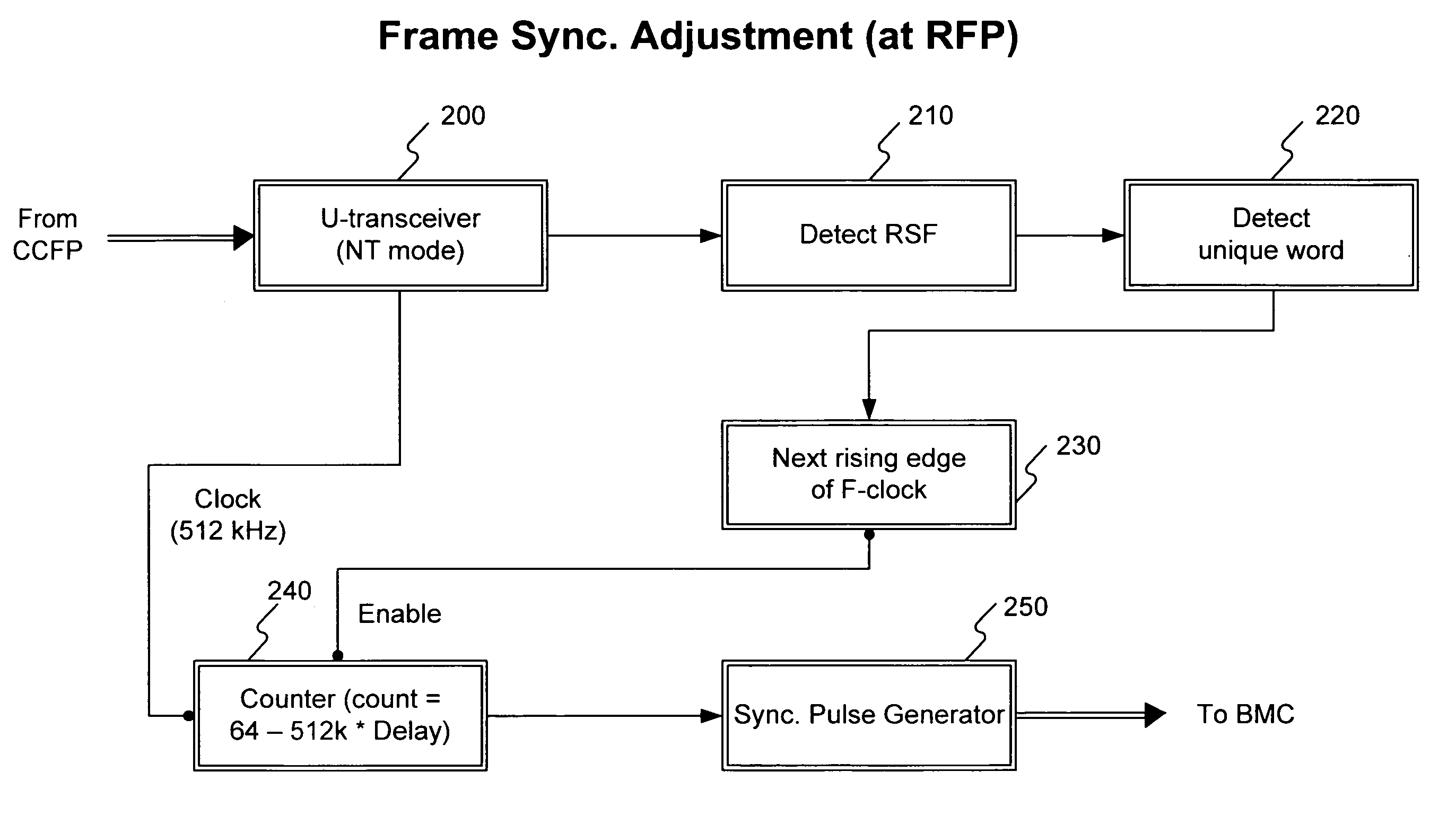
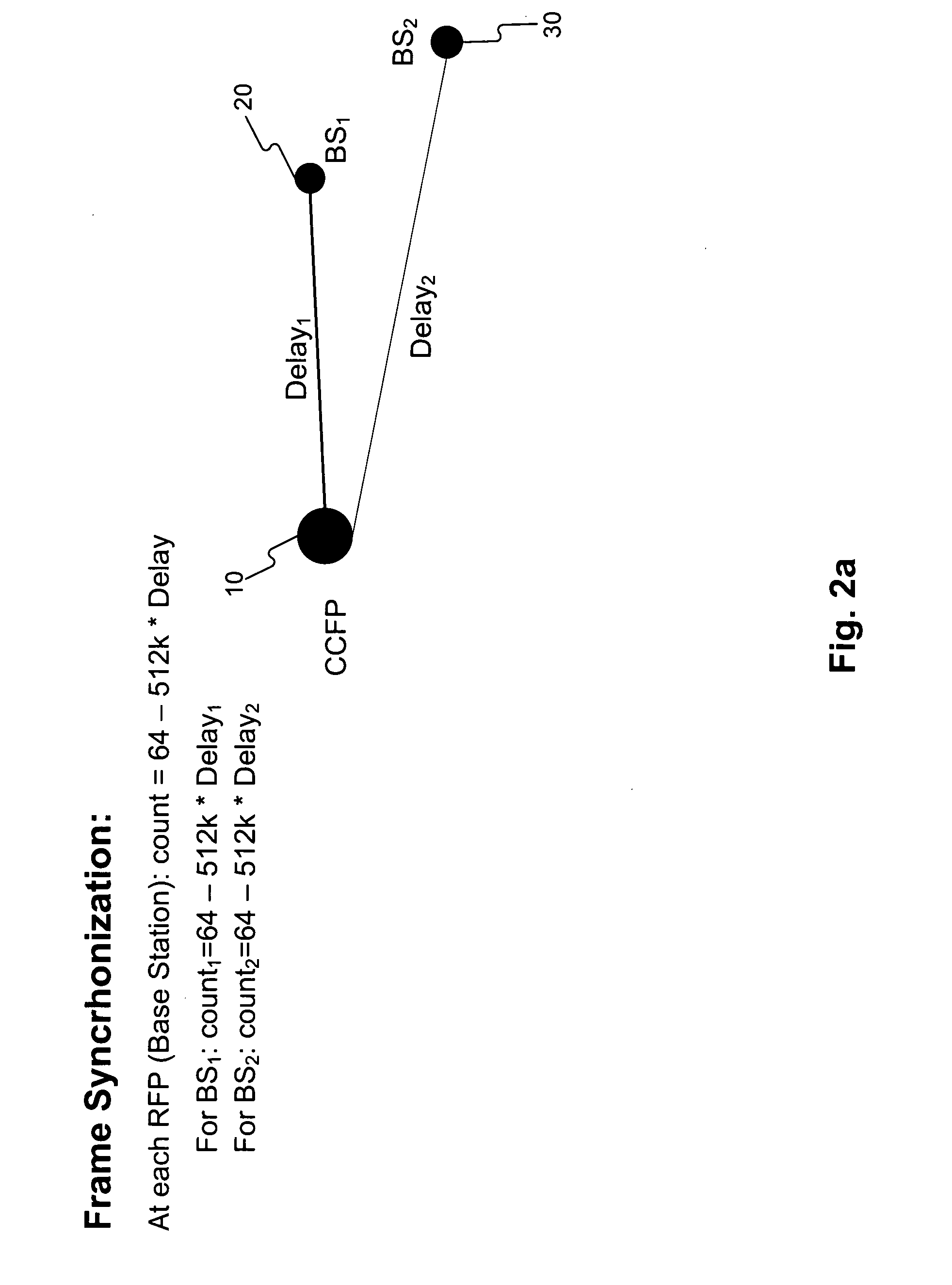
[0023]In order to synchronize frames in the present invention, the delay between transmission of a signal from CCFP 10 and its reception at each RFP must be known. Each of RFPs 20, 30, and 40 will have a unique delay due to its unique distance from the CCFP 10. These delays are constants and can be measured either by a delay measuring device or by a distance measurement at initial installation.

[0024]In the latter case, the delay is calculated by the following formula:

Delay=(Distance from RFP to CCFP) / (phase velocity of EM wave in the wire).

A typical phase velocity in the wire is about 2*108 meters / second. Once the propagation delay has been determined for each base station, this value is stored in a nonvolat...


PUM


Abstract

A method of timing in a multi-cell system requiring synchronization of frames in transmission is provided. Transceivers of a wired data interface between a central controller and multiple base stations are synchronized to a frame timing clock up to a difference in propagation delays between the central controller and multiple base stations. The propagation delays are considered as constants, are measured, and are stored in each base station. A unique word is regularly inserted in the data transmitted by the central controller, at a fixed interval. When this unique word is detected by the base station within a fixed period of the frame timing clock, a frame signal delay is initiated at the next rising edge of each frame timing clock. This frame signal delay is equal to the period of the frame timing clock minus the propagation delay. At the end of the frame delay, the frame data is transmitted, and all frames are simultaneously transmitted from different base stations.

Description

BACKGROUND OF THE INVENTION[0001]A. Field of the Invention[0002]The present invention relates to signal synchronization in multi-cell communication systems. The disclosed method and apparatus are applicable to all communication systems requiring frame synchronization, especially those using synchronized interfaces. These systems include, but are not limited to, Time Division Multiple Access (TDMA) and Code Division Multiple Access (CDMA) systems. The present invention is intended for use in, for example, wireless communications, such as cordless telephone systems; low-tier, low-power, multi-cell personal communications services; wireless local loops (WLL); wireless local area networks (LAN); and wireless private branch exchanges (PBX).[0003]B. Description of the Related Art[0004]FIG. 1 shows a typical configuration of a conventional mobile communication system. A central control fixed part (CCFP) 10 is typically connected to several radio frequency parts (RFP) 20, 30, and 40, via tw...

Claims


Application Information

Patent Timeline
Patent Type & Authority Patents(United States)
IPC IPC(8): H04J3/06H04B7/26H04Q7/20
CPCH04J3/0682H04J3/0602
Inventor LU, CHUN CHIANWANN, CHIN-DERHO, JUL-KUANG
Owner IND TECH RES INST
Features
  • R&D
  • Intellectual Property
  • Life Sciences
  • Materials
  • Tech Scout
  • Unparalleled Data Quality
  • Higher Quality Content
  • 60% Fewer Hallucinations
Learn More