Stress detection method for sensor device with multiple axis sensor and sensor device employing this method

a sensor device and multiple axis technology, applied in the direction of force/torque/work measurement apparatus, instruments, calibration apparatus, etc., can solve the problems of navigation device mounting, unnecessary braking or unstable state, spin judgment,

Inactive Publication Date: 2008-01-22
TAMAGAWA SEIKI CO LTD
View PDF16 Cites 33 Cited by
  • Summary
  • Abstract
  • Description
  • Claims
  • Application Information

AI Technical Summary

Benefits of technology

[0032]According to the present invention, because the stress component perpendicular to the detection axis can be eliminated, when the sensor device according to the present invention is mounted on the device for detection, the sensor device can be used by means of only the input of the installation angle θ irrespective of the specific mount angle. Furthermore, the sensor device can also be constituted to sense the mount angle autonomously instead of the mount angle being inputted from the outside. Therefore, the sensor device to which the present invention is applied can be used generically.

Problems solved by technology

Further, when an acceleration sensor for sensing vehicle acceleration is used for vehicle brake control and so forth, a fault with the acceleration sensor causes unnecessary braking or an unstable state such as vehicle spin is judged.
The problem where the direction of the detection axis in which the acceleration sensor detects and the direction of the physical quantity that is actually delivered to the sensor do not match occurs in the following case, for example.
However, generally, in cases where the navigation device is mounted in a vehicle, there are frequent cases where the navigation device is mounted tilted due to restrictions with the vehicle-mounting structure and the relationship with the interior and so forth.
As a result, detection errors occur so that accurate positional measurement is difficult.
Therefore, in the case of Japanese Patent Application Laid Open No. 2003-227844, sensor devices with corresponding sensor mount angles must be prepared for each specified mount angle and therefore cannot be used generically for a variety of specified mount angles.

Method used


Image

  • Stress detection method for sensor device with multiple axis sensor and sensor device employing this method
  • Stress detection method for sensor device with multiple axis sensor and sensor device employing this method
  • Stress detection method for sensor device with multiple axis sensor and sensor device employing this method

Examples


first embodiment

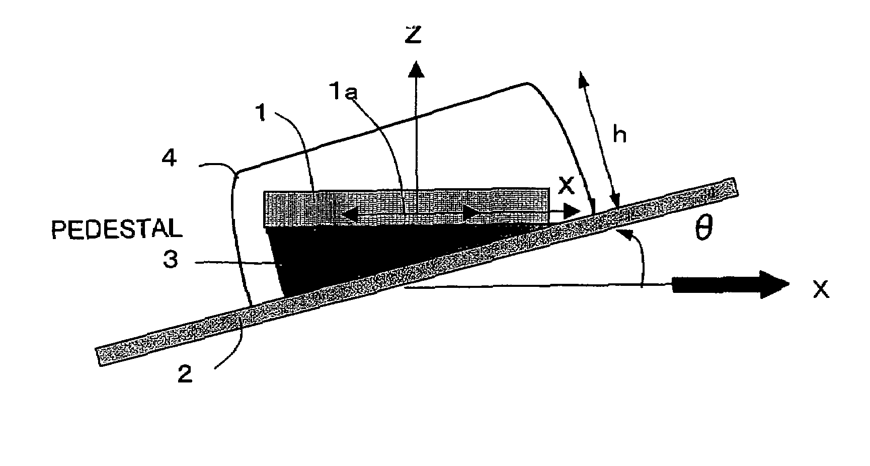
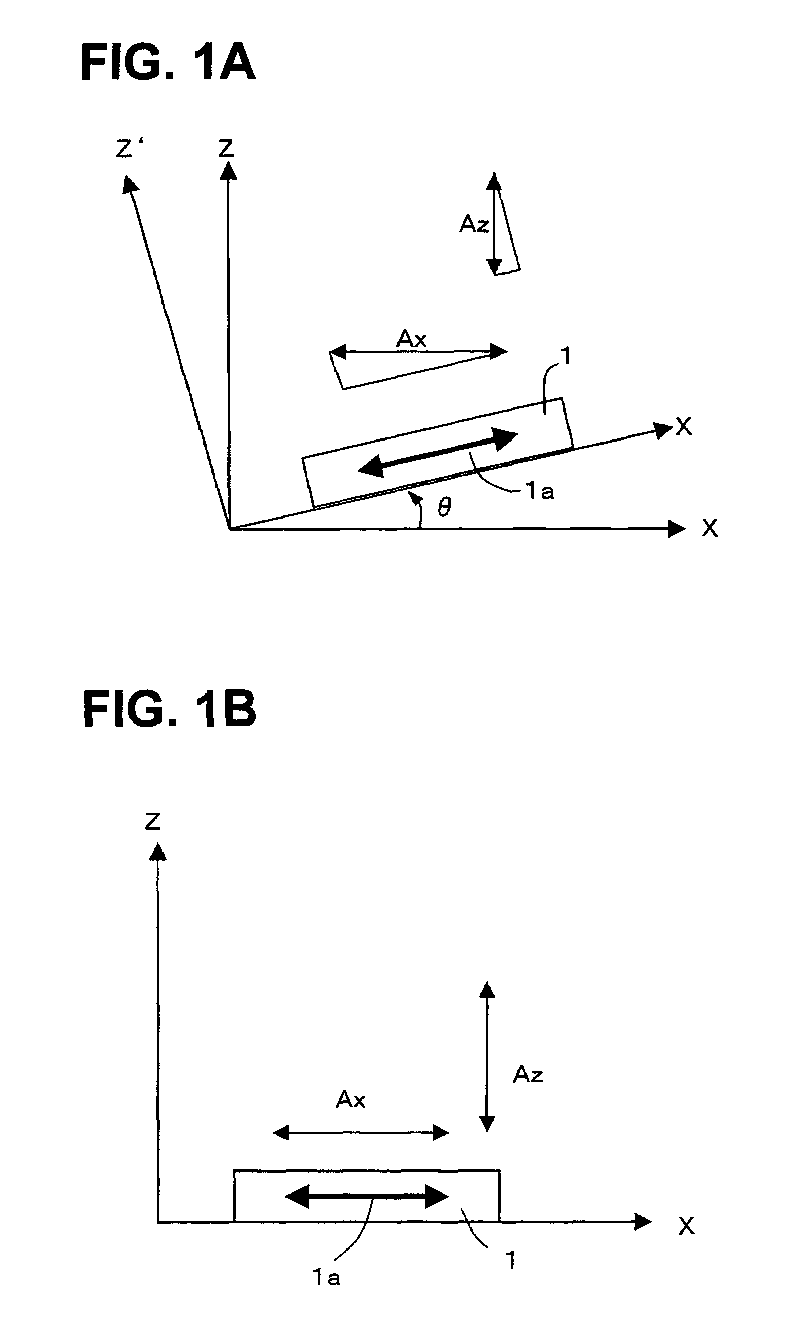
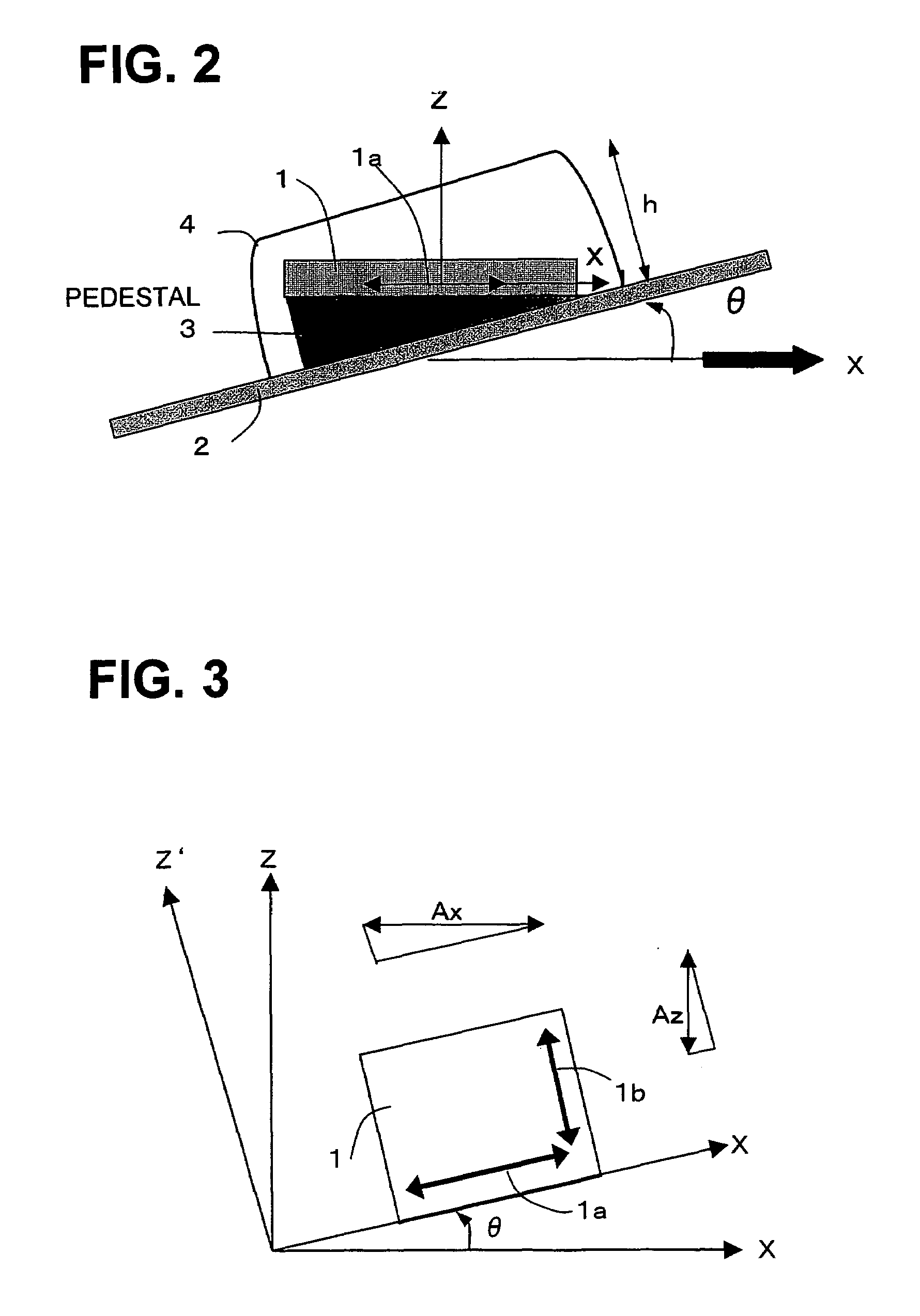
[0069]FIG. 3 illustrates the operating principles of the first embodiment of the present invention.

[0070]In the conventional example shown in FIG. 1, a force sensor that has only one detection axis is used in order to detect the stress in the detected axis direction of the object. In contrast, in the first embodiment according to the present invention, a 2-axis detection output is used.

[0071]As an embodiment example, in the example shown in FIG. 3, a 2-axis detection output, namely of an axis in a horizontal direction (X-axis) and an axis in a vertical direction (Z axis), is used.

[0072]That is, as shown in FIG. 3, the force sensor 1 has force sensors 1a and 1b for sensing stress components corresponding with the X-axis and Z-axis directions respectively. In a case where the force sensor 1 is mounted tilted by θ with respect to the detected axis X of the object, the stress component Apx sensed by the force sensor 1a and the stress component Apz sensed by the force-sensor 1b are produ...

second embodiment

[0083]FIGS. 5A to 5C illustrate the operating principles of the second embodiment of the present invention. This embodiment detects the stress on the detected axis by using three force sensors.

[0084]FIG. 5A illustrates the stress component of the x and y axes, which are two axes in mutually opposite directions by angle Φ from the detected axis X when stress F1 is provided on the detected axis X (or Y axis, described as the X axis hereinbelow). Two force sensors a and b for detecting the stress component along the x and y axes are provided.

[0085]Stress components Fx1 and Fy1, which are detected by force sensors a and b respectively, are as follows.

Fx1=αx×F1×cos Φ

Fy1=αy×F1×cos Φ

[0086]The sensor further comprises a force sensor c, which senses the stress in the Z-axis direction as a third force sensor. FIG. 5B illustrates the stress detection of the force sensor c.

[0087]Gravity (F2) acts on the force sensor c as stress in the Z-axis direction. Therefore, the stress component Fz1, which...

embodiment example 1

[0117]FIG. 6 is an explanatory view of an embodiment example in which the force sensor device to which the present invention is applied is constituted by a multiple-axis resistor-type force sensor chip.

[0118]FIG. 6A is a top view of a fabricated sensor chip that is mounted in a package 10 of the force sensor device. FIG. 6B is a cross-sectional view along the line A-A′.

[0119]As the fabrication step, piezoresistive elements 14 and A1 wiring are first formed on the surface of an SOI substrate that is obtained by bonding the Si substrate 100, on which a thermal oxide film SiO2 101 is formed, to a second Si substrate 102 by means of anodic coupling as shown in FIG. 6A. FIG. 6A shows only the piezoresistors 14.

[0120]Next, region 16 is etched by subjecting the second Si layer 102 to Deep RIE or the like. In addition, etching is performed from the side of the first Si substrate 100. At this time, because the oxide film layer (SiO2) 101 prevents etching of the second Si layer 102, region 16...


PUM

PropertyMeasurementUnit
angleaaaaaaaaaa
stressaaaaaaaaaa
stressaaaaaaaaaa

Abstract

The present invention provides the stress detection method for force sensor device with multiple axis sensor device and force sensor device employing this method, whose installation angle is arbitrary. The stress detection method includes, first and second force sensors whose detection axes are orthogonal to each other. When the detection axis of first force sensor forms angle θ with direction of detected stress Ax, and the stress component of direction perpendicular to direction of the detected stress Ax is Az, output Apx of the axis direction of first force sensor is found as Apx=αx (Ax×cos θ+Az×sin θ), and output Apz of the axis direction of the second force sensor is found as Apz=αz (Ax×sin θ+Az×cos θ), and, when αx and αz are detection sensitivity coefficients of first and second force sensors respectively, the detection sensitivity coefficient αz of second force sensor is set as αz=αx tan θ, and the detected stress Ax is found as Ax=(Apx−Apz) / αx(cos θ−tan θ×sin θ).

Description

BACKGROUND OF THE INVENTION[0001]1. Field of the Invention[0002]The present invention relates to a stress detection method for a force sensor device with a multiple axis sensor and a force sensor device employing this method.[0003]2. Description of the Related Art[0004]For varied control of mobile bodies such as automobiles and ships, robots and machine manufacturing equipment or mobile devices that are held and used by users such as notebook PCs, cellular phones, PDAs (Personal Digital Assistants), DVCs (Digital Video Cameras), DSCs (Digital Still Cameras) and so forth, for example, detection of the stress on all or part of a target according to the control objective is essential. Acceleration can be sensed by sensing the stress on the basis of the acceleration acting on all or part of the target.[0005]A variety of devices for detecting this stress or acceleration has been developed conventionally. As one such device, a device that forms a gauge resistance on a semiconductor substr...

Claims


Application Information

Patent Timeline
Patent Type & Authority Patents(United States)
IPC IPC(8): G01P15/125G01L5/16G01P15/12
CPCG01P15/123G01P21/00G01P15/18G01P2015/084G01L5/16
Inventor HANAZAWA, TOSHIOONO, MASAAKIMIYASHITA, TSUTOMUTOKUNAGA, HIROSHIISHIKAWA, HIROSHI
Owner TAMAGAWA SEIKI CO LTD
Why Eureka
Try Eureka