Roots type fluid machine

a fluid machine and root technology, applied in the direction of machines/engines, liquid fuel engines, rotary piston liquid engines, etc., can solve the problems of reducing the performance of the roots compressor, large noise generation, and noise problems such as nois

Active Publication Date: 2008-01-22
TOYOTA IND CORP
View PDF7 Cites 11 Cited by
  • Summary
  • Abstract
  • Description
  • Claims
  • Application Information

AI Technical Summary

Problems solved by technology

When the fluid is released to the rotor chamber, a large noise is generated.
In the roots compressor having such a phase shift, the lobe portion of one rotor and the well portion of the other rotor interfere with each other, which causes trouble such as noise.
If a large clearance is provided, however, leak of the fluid through the clearance will be increased thereby to reduce the performance of the roots compressor.
For this reason, when the high performance of the roots compressor is desired, the clearance must be small, which makes it hard to avoid the interference between the rotors due to the phase shift.

Method used


Image

  • Roots type fluid machine
  • Roots type fluid machine
  • Roots type fluid machine

Examples


Embodiment Construction

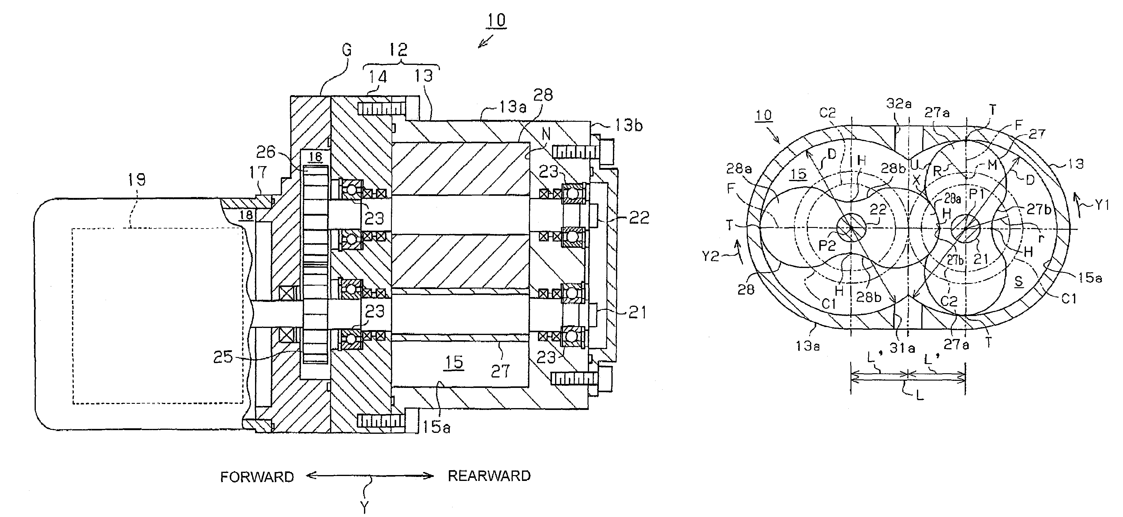
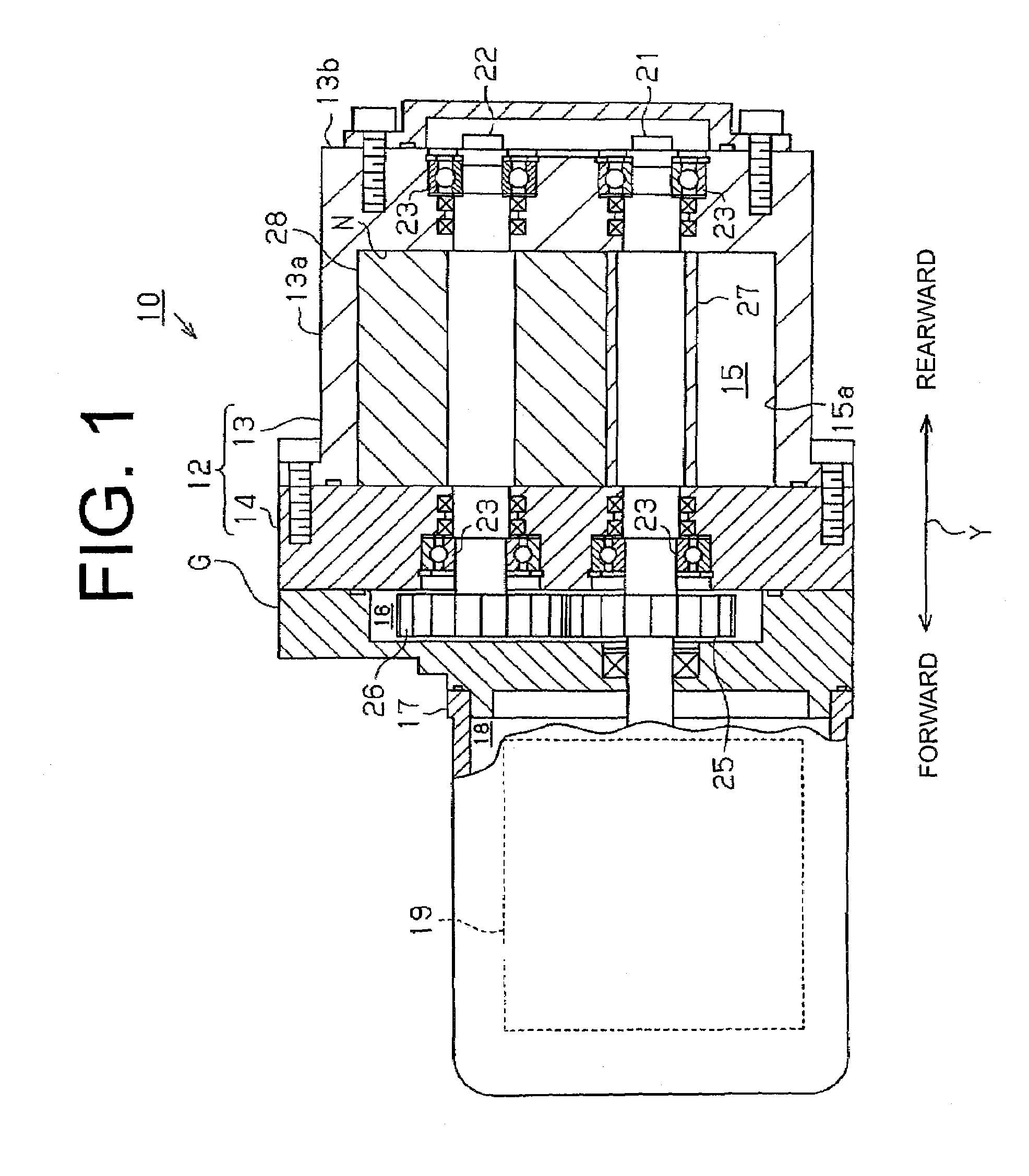
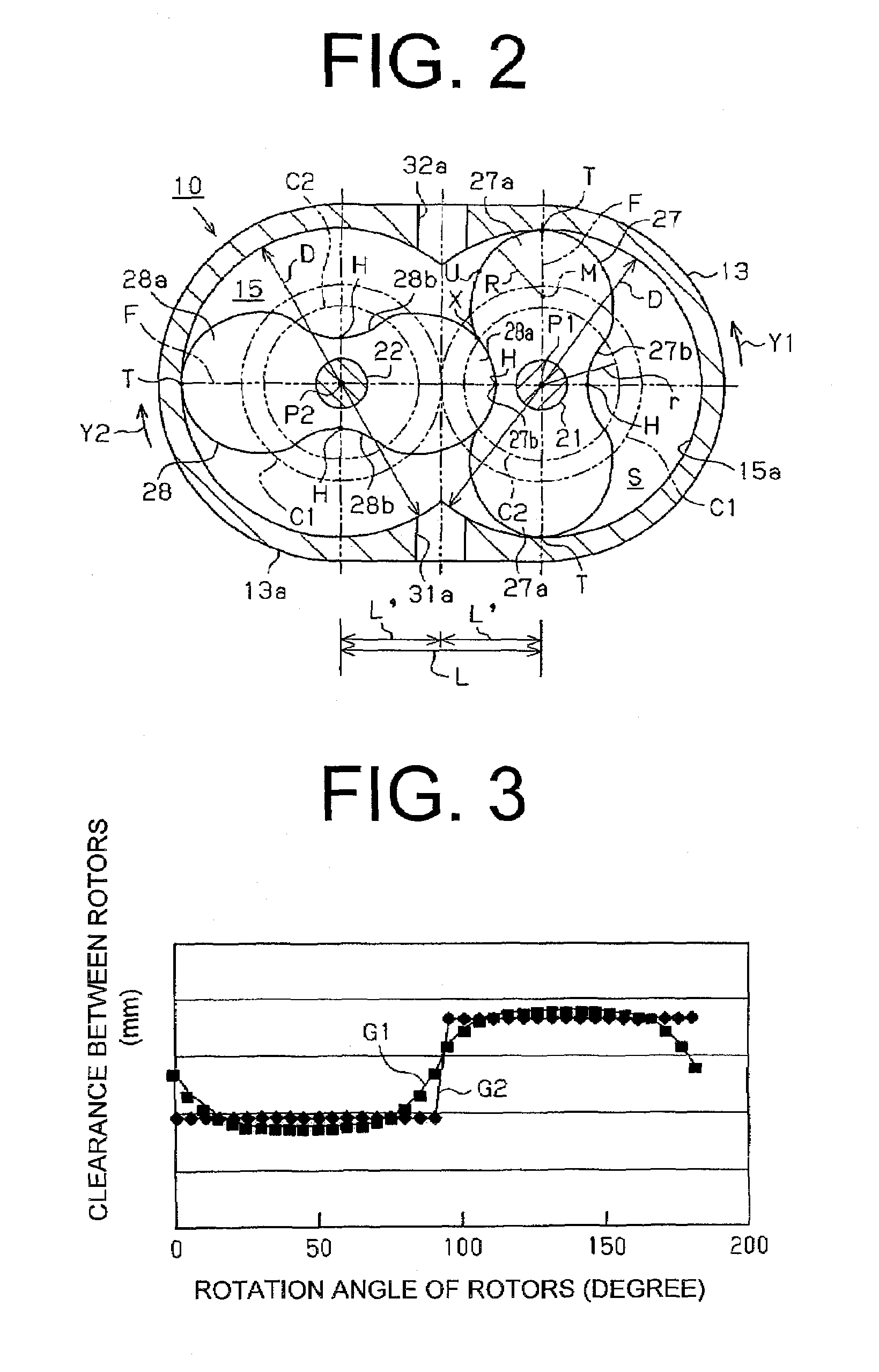
[0016]The following will describe the first embodiment of a roots type fluid machine of the present invention as embodied in a roots compressor with reference to FIGS. 1 through 3. It is noted that forward and rearward directions of the roots compressor are indicated by arrow Y of FIG. 1.

[0017]Referring to FIG. 1, the roots compressor 10 has a housing assembly (or a compressor housing) which includes a rotor housing 12, a gear housing G which is joined to the front end of the rotor housing 12, and a motor housing 17 which is joined to the front end of the gear housing G. The rotor housing 12 includes a first housing 13 and a second housing 14 which is joined to the front end of the first housing 13. The first housing 13 has a cylindrical shape having one end thereof closed, and has a cylindrical peripheral wall 13a and an end wall 13b which forms the bottom of the first housing 13.

[0018]The compressor housing has a rotor chamber 15 defined between the first housing 13 and the second...


PUM


Abstract

A roots type fluid machine includes a housing, a pair of parallel rotary shafts and two-lobe rotors. Each rotor includes two lobe portions and two well portions. Each lobe portion has a profile of convex arc with a radius R and each well portion has a profile of concave arc which is an envelope of the convex arc of the lobe portion. The rotor has a configuration defined by a curve which includes the convex arc, the concave arc and further an involute curve with a base radius r between the convex and concave arcs. The base radius r is set in a range L / (2√{square root over ( )}2)<r<0.3(√{square root over ( )}2)L where distance between axes of the rotary shafts is L, and the radius R is set in a range {(√{square root over ( )}2) / 16}πL<R<{(27−5√{square root over ( )}2) / 56}L.

Description

CROSS-REFERENCE TO RELATED APPLICATION[0001]This application claims priority to Japanese Patent Application No. 2005-355957 filed Dec. 9, 2006.BACKGROUND OF THE INVENTION[0002]The present invention relates to a roots type fluid machine wherein a pair of parallel rotary shafts is rotatably supported by a housing and each rotary shaft has disposed thereon a rotor which has at least two lobe portions and two well portions so that the rotors engage with each other, and each rotor is located in a rotor chamber of the housing.[0003]A roots compressor that serves as a roots type fluid machine has a housing and a pair of two-lobe or three-lobe rotors located in a rotor chamber of the housing. The rotors are located in the rotor chamber so as to have minimum clearance with the peripheral surface of the rotor chamber and also between the rotors. The two-lobe rotors engage with each other every 90 degrees of rotation of the rotors and the three-lobe rotors every 60 degrees of rotation of the r...

Claims


Application Information

Patent Timeline
Patent Type & Authority Patents(United States)
IPC IPC(8): F01C21/10F03C2/00F04C2/00
CPCF04C18/084F04C18/126
Inventor HIRANO, TAKAYUKIYAMADA, KAZUHOFUJII, TOSHIRO
Owner TOYOTA IND CORP
Why Eureka
Try Eureka