Cutting Insert and Indexable Tooth Cutting Tool Using the Same

a cutting tool and indexable technology, applied in the direction of gear teeth, manufacturing tools, gear teeth, etc., can solve the problems of poor cutting performance, high cutting resistance at cutting, and easy generation of vibrations

Active Publication Date: 2011-10-20
TUNGALOY CORP
View PDF15 Cites 18 Cited by
  • Summary
  • Abstract
  • Description
  • Claims
  • Application Information

AI Technical Summary

Problems solved by technology

In a case where the cutting insert is mounted on an insert mounting seat, an axial rake angle is negative, thereby leading to poor cutting performance and high cutting resistance at cutting.
Therefore, chattering vibrations tend to be easily generated, which raises a problem of inviting deg...

Method used


Image

  • Cutting Insert and Indexable Tooth Cutting Tool Using the Same
  • Cutting Insert and Indexable Tooth Cutting Tool Using the Same
  • Cutting Insert and Indexable Tooth Cutting Tool Using the Same

Examples


Embodiment Construction

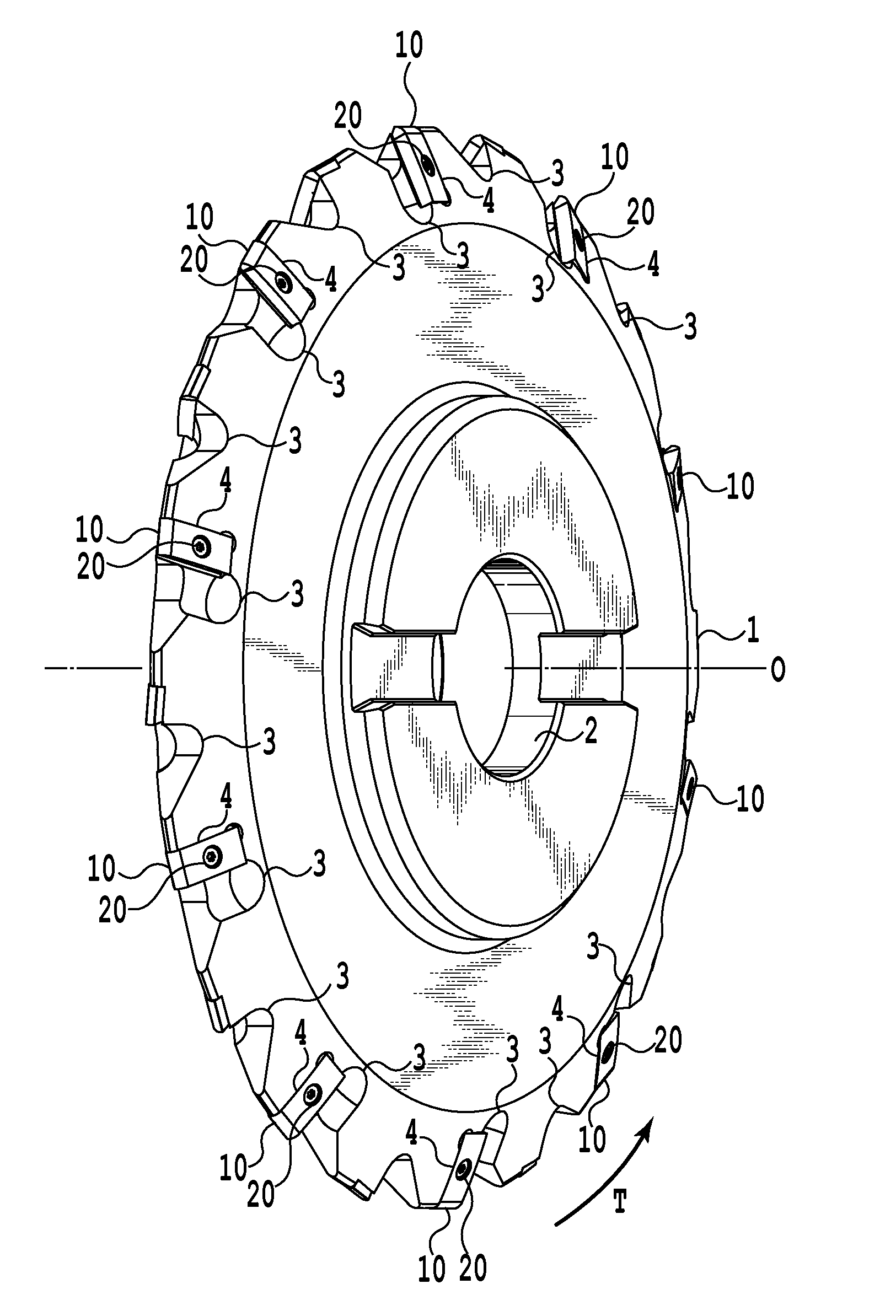
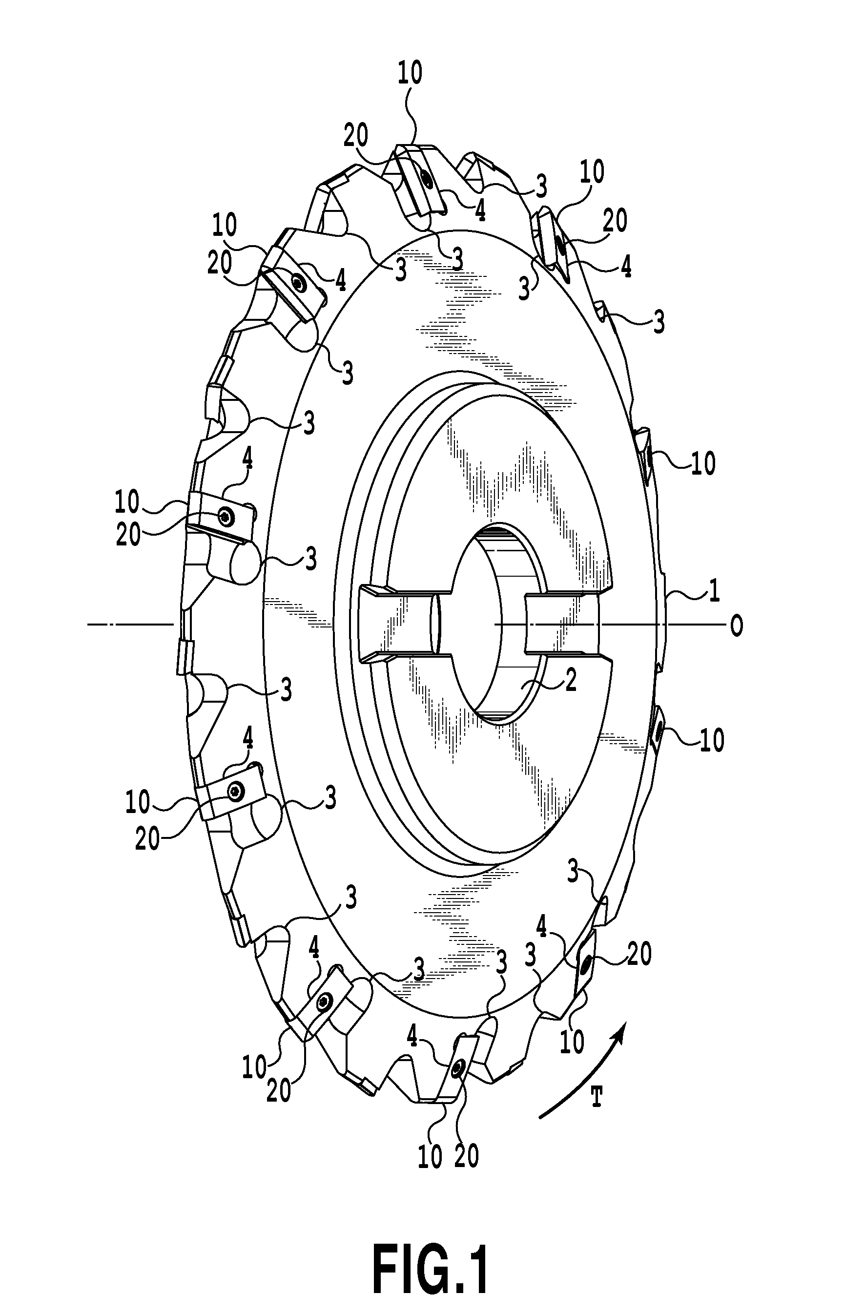
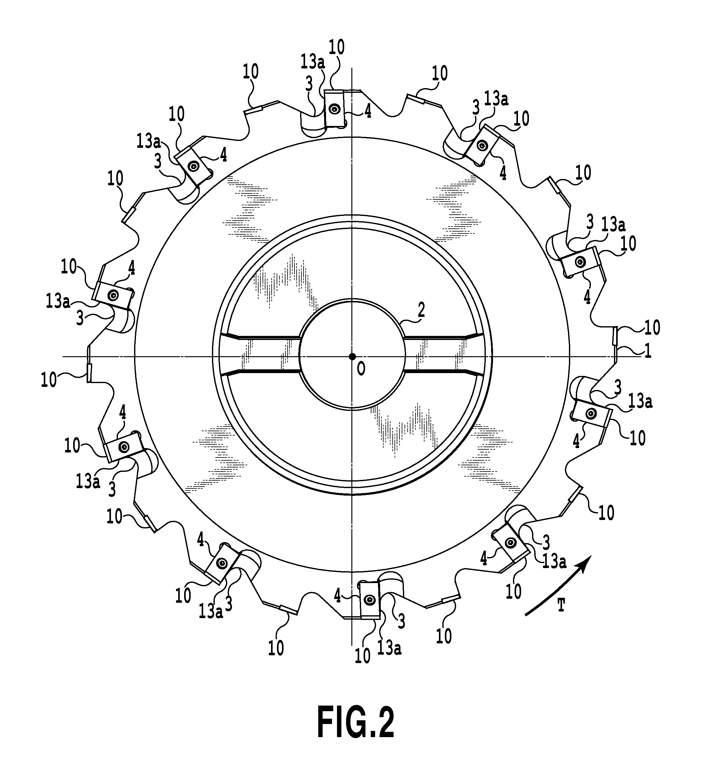
[0034]Hereinafter, an embodiment of a cutting insert according to the present invention and an indexable cutting tool using the cutting insert will be described with reference to FIG. 1 to FIG. 8.

[0035]A tooth cutter according to the present embodiment, as shown in FIG. 1 to FIG. 3, comprises a tool body 1, insert bodies 10, and mounting screws 20. The tool body 1 is formed in a substantial disc shape to be rotated around an axis line O. The insert body 10 is removably mounted on an outer peripheral portion of the tool body 1 as an edge portion. The mounting screw 20 is used for mounting the insert body 10 on the tool body 1.

[0036]The tool body 1 is made of a steel material or the like and is provided with a through hole 2, a plurality of chip pockets 3 and a plurality of insert mounting seats 4. The through hole 2 is formed to penetrate through a central portion of the tool body 1 along an axis line O and is used for mounting the tool body 1 on a main spindle of a working machine. ...


PUM

PropertyMeasurementUnit
Angleaaaaaaaaaa
Shapeaaaaaaaaaa

Abstract

A cutting insert is removably mountable on an insert seat formed in a peripheral of a tool body rotated around an axis O and of substantial disc shape. The cutting insert includes a substantially planar insert body of a substantially square shape in plan view, a flank at an upper face of the body, a rake face at a side of the body intersecting with the flank, and a cutting edge at an intersection ridge between the rake face and the flank. The cutting edge is a substantial involute in side view of the body, the rake face is inclined to an inside of the body from an upper toward a lower face, and at least a front end arranged in a peripheral of the tool body is concave constituting a part of a substantially conical side face.

Description

[0001]This application is a Continuation of International Application No. PCT / JP2009 / 007215, filed Dec. 24, 2009 and published as WO 2010 / 073681 on Jul. 1, 2010, which claims priority to Japanese Patent Application No. 2008-329919, filed Dec. 25, 2008. The contents of the aforementioned applications are incorporated by reference herein in their entirety.BACKGROUND OF THE INVENTION[0002]1. Field of the Invention[0003]The present invention relates to a cutting insert used in tooth cutting work for cutting tooth grooves of a gear or the like and an indexable tooth cutting tool using the cutting insert, in particular mainly for cutting an involute gear.[0004]2. Description of the Related Art[0005]A formed tooth cutting tool is used in tooth cutting work by a forming method of cutting out a tooth profile of a gear by an edge profile having the same contour as that of the tooth profile of the gear to be cut. In a conventionally known formed tooth cutting tool, cutting inserts are mechanic...

Claims


Application Information

Patent Timeline
IPC IPC(8): B23C5/08B23C5/20
CPCB23F21/146Y10T407/245Y10T407/1924Y10T407/17Y10T407/1942Y10T407/173
Inventor YOSHIDA, SATORU
Owner TUNGALOY CORP
Why Eureka
Try Eureka