Interlocking filtration device

a filter device and interlocking technology, applied in the direction of filtration separation, colloidal chemistry, separation process, etc., can solve the problems of large air filter for such use, large gap disadvantage, and inability to adapt to alternate applications

Active Publication Date: 2008-01-22
TICKNOR KIRK
View PDF26 Cites 18 Cited by
  • Summary
  • Abstract
  • Description
  • Claims
  • Application Information

AI Technical Summary

Benefits of technology

[0021]Therefore, a feature and advantage of the present invention is its simplicity of installation for the mechanic.

Problems solved by technology

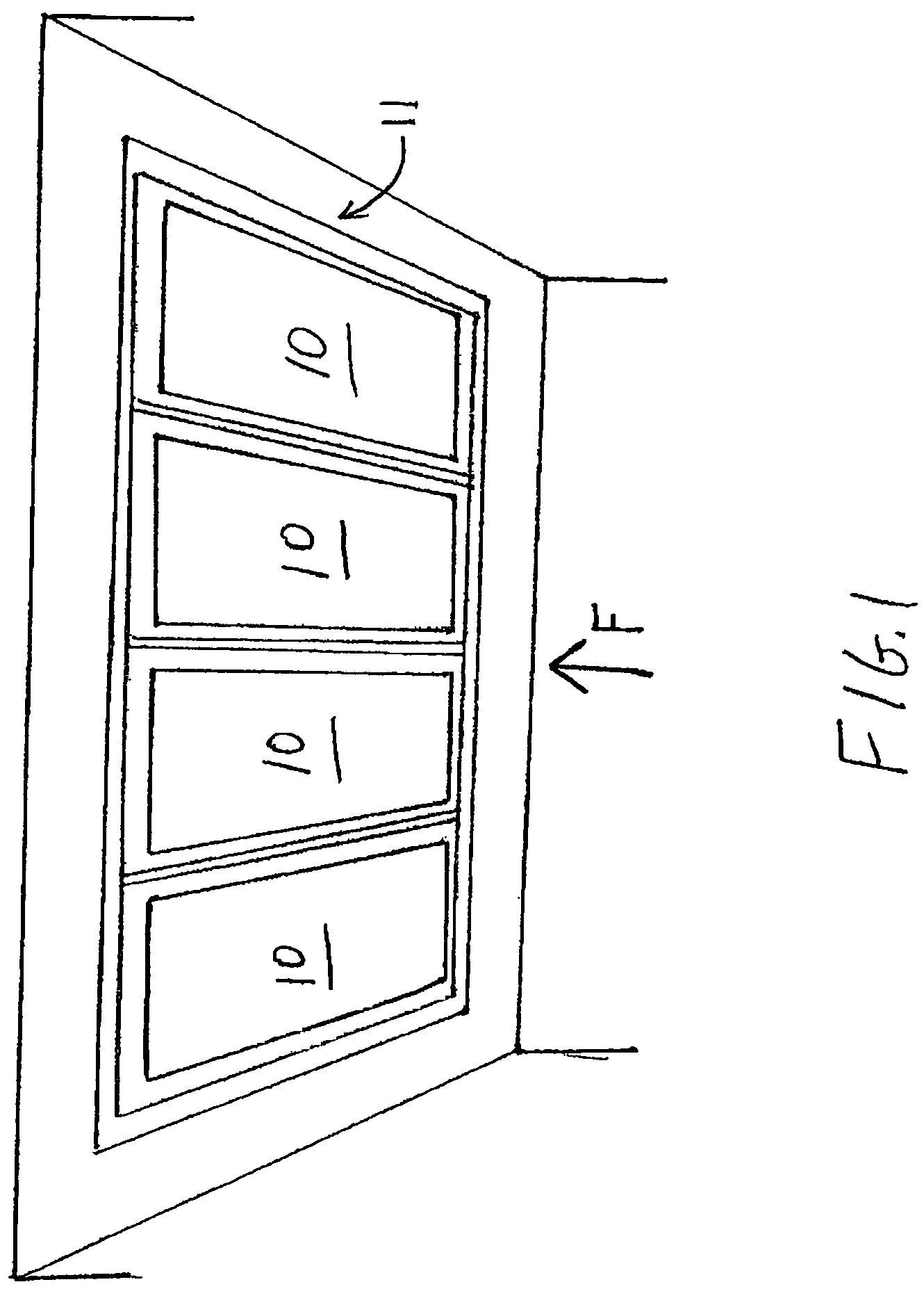
Ventilation ductwork and filter banks may vary in dimensions and, as a result, an air filter that may be of appropriate size for one application may not be suitable for an alternate application.
A single very large air filter for such use would likely be prohibitively expensive, cumbersome to install, and / or difficult to support.
Traditional air filters of a filter bank, as slidably installed into a traditional air handler, often have a small gap disadvantageously therebetween.
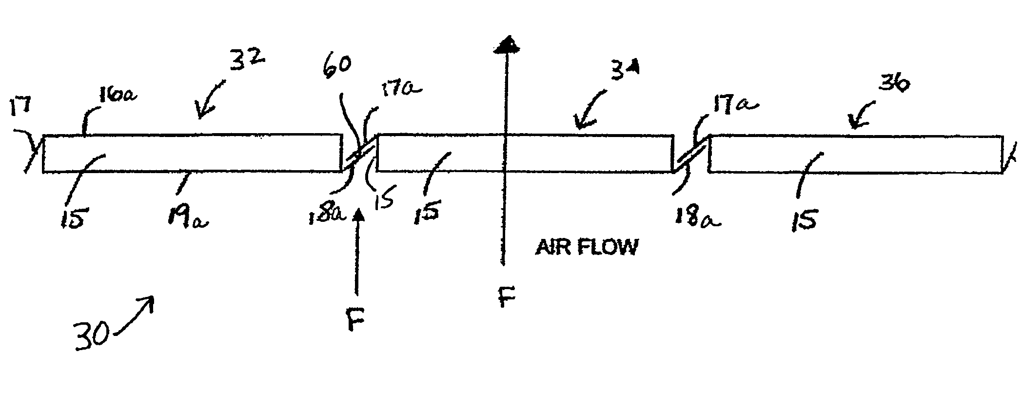
Thus, whenever multiple air filters are juxtaposed one to another, a potential problem arises: the possibility of air flow through gaps between adjacent air filters.
Bypassing the filtering portion of an air filter, air containing particulate matter including allergens and impurities may circulate under pressure throughout a building, exposing employees, patrons, or inhabitants to the harmful effects of its contaminants.
Even when the gap between filters is narrow relative to the filter width, the volume of unfiltered air delivered to a building over time may be sufficient to produce detrimental effects on air quality.
The effects may be particularly hazardous to people with asthma, allergies or other respiratory conditions.
As the efficiency of air filters increases, with some filters operating at 99.9% efficiency, the detrimental effects caused by unfiltered air flowing through a ventilation system becomes even more significant.
Furthermore, in addition to adverse effects on individuals and operations within a building structure, unfiltered air flow may also induce mechanical problems within the ventilation system itself.
Dust particles may be deposited on the heating and cooling coils, clogging the coils and impeding proper ventilation system operation.
Cleaning such coils is both time consuming and expensive.
However, HEPA filters may also be quite expensive, particularly when a large number of them are required for a filter bank.
Although adequate for its intended purpose, such a design is disadvantageous in view of the present invention due to the requirement of using a connector piece separate from the filter itself.
Because the connector piece is inserted separately from the air filter, such filter installation process would disadvantageously be more time-consuming and cumbersome than that of installing filters alone.
There is also the risk that an installer may inadvertently drop a connector piece into the filter bank and be forced to extract and reposition it, prolonging the installation process.
The sealing elements may be variously shaped and extended outward, however, they are designed to seal the cartridge and fit it within a housing; thus, such a cartridge does not address the need for blocking air flow between multiple framed cartridges.
As a result, the positioning of adjacent filters is not adjustable in a manner that may accommodate variably sized filter locations.

Method used


Image

  • Interlocking filtration device
  • Interlocking filtration device
  • Interlocking filtration device

Examples


Embodiment Construction

[0030]In describing the preferred and alternate embodiments of the present invention, as illustrated in the figures and / or described herein, specific terminology is employed for the sake of clarity. The invention, however, is not intended to be limited to the specific terminology so selected, and it is to be understood that each specific element includes all technical equivalents that operate in a similar manner to accomplish similar functions.

[0031]Thus, exemplary embodiments of the invention are presented herein; however, the invention may be embodied in a variety of alternative forms, as will be apparent to those skilled in the art. To facilitate understanding of the invention, and provide a basis for the claims, various figures are included in the description. The figures are not drawn to scale and related elements may be omitted so as to emphasize the novel features of the invention. Structural and functional details depicted in the figures are provided for the purpose of teach...


PUM

PropertyMeasurementUnit
lengthaaaaaaaaaa
adhesiveaaaaaaaaaa
sizeaaaaaaaaaa

Abstract

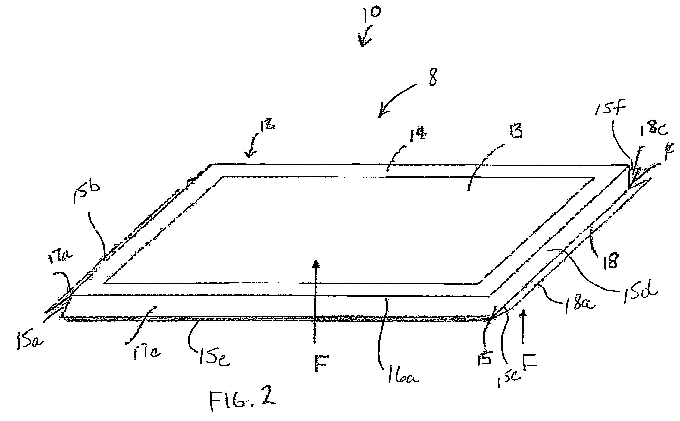
A filtration device adapted for adjustably interlocking with adjacent filtration devices in a filter bank, wherein inversely disposed flaps on opposing sidewalls, such us an upper flap disposed along a first sidewall and a lower flap disposed along an opposing sidewall, overlap to interlock and prevent air flow between adjacent filters. Each flap may comprise a single member, or may include multiple folded sections, and may be color coded or provided with installation instructions, may be manufactured integrally with an air filter frame, or may be formed separately and adhered to the frame prior to filter installation, and a flap may also include an adhesive for adhering interlocking flaps together.

Description

FIELD OF THE INVENTION[0001]The present invention relates in general to filtering devices. In particular, the invention relates to air filter devices for use in filter bank applications in which multiple adjacent air filters are deployed.BACKGROUND OF THE INVENTION[0002]Air filters are generally known in the art and are employed in a variety of contexts including internal combustion engines, gas compressors and heating and ventilation systems. Designed to remove particulate matter from the air, a typical air filter is composed of a filtering material, often paper or foam, and a frame or housing that supports the filtering material. Typically an air filter is placed in the path of an air flow, such as proximate an air intake.[0003]For an air filter to function properly and effectively, the air flow path should be directed toward and forced through the filtering portion of the air filter so that impurities in the air are removed. Thus, an air filter should be arranged to maximize air ...

Claims


Application Information

Patent Timeline
Patent Type & Authority Patents(United States)
IPC IPC(8): B01D50/00B01D46/00
CPCB01D46/002B01D46/10B01D46/12B01D2265/024Y10S55/31B01D46/58
Inventor TICKNOR, KIRK
Owner TICKNOR KIRK
Why Eureka
Try Eureka