Survey system

a technology of a survey system and a survey instrument, which is applied in the direction of instruments, devices using optical means, angle measurement, etc., can solve the problems of reducing revealing the automatic tracking type of the survey instrument, and unable to shorten so as to achieve an efficient surveying operation and reduce the burden on the operator. , the effect of shortening the time required for the survey

Active Publication Date: 2008-01-22
KK TOPCON
View PDF6 Cites 41 Cited by
  • Summary
  • Abstract
  • Description
  • Claims
  • Application Information

AI Technical Summary

Benefits of technology

[0013]According to the invention of claim 1, an angular difference is calculated between the target direction angle measured by the surveying instrument and the surveying-instrument direction angle measured by the target at the last measurement, and an estimated target direction angle for the present measurement is calculated from the surveying-instrument direction angle measured by the target at the present measurement performed after the target has been moved and from the angular difference calculated at the last measurement, whereby the instrument body can be directed in the direction of the estimated target direction angle at once. Therefore, the surveying instrument can find the target placed at the measurement point in a short time, can complete the measurement, and can perform an efficient surveying operation. Since the automatic tracking type surveying instrument has, of course, no problem even if it loses sight of the target, a burden imposed on the operator is lessened.
[0014]According to the invention of claim 2, like the invention according to claim 1, an angular difference is calculated between the target direction angle measured by the surveying instrument and the surveying-instrument direction angle measured by the target at the last measurement, and an estimated target direction angle for the present measurement is calculated from the surveying-instrument direction angle measured by the target at the present measurement performed after the target has been moved and from the angular difference calculated at the last measurement, whereby the instrument body can be directed in the direction of the estimated target direction angle at once. Therefore, the same effect as in the invention according to claim 1 is fulfilled.
[0015]According to the invention of claim 3, additionally, the rotation means determines a rotational direction having a smaller angular difference selected from between a clockwise angular difference and a counterclockwise angular difference, concerning a present direction angle at which the body of the surveying instrument is directed and the estimated target direction angle. Therefore, since the surveying instrument catches the target by rotating the instrument body by the minimum rotation angle, the time required for the measurement can be made shorter.
[0016]According to the invention of claim 4, additionally, the angular-difference calculating means calculates a representative value (e.g., an average value and a weighted average) of angular differences that have hitherto been obtained whenever the angular differences are calculated, and the target-direction-angle estimating means uses the representative value as the angular difference. Therefore, the accuracy of the angular difference improves, and the target direction angle can be estimated more accurately after the target has been moved. Therefore, the target can be caught more swiftly, and the time required for the measurement can be made even shorter. Since the influence of numerical values deviating extremely from an average value is removed especially by using a weighted average, the accuracy of the angular difference becomes even higher, and the target direction angle can be accurately estimated after the target has been moved. Therefore, the target can be caught more swiftly, and the time required for the measurement can be made even shorter.
[0017]According to the invention of claim 5, additionally, the target includes a guide light transmitter that emits guide light indicating a direction of the target, and the surveying instrument includes a direction detector that detects the direction of the target by receiving the guide light. Therefore, the surveying instrument can find the target more swiftly, and the time required for the measurement can be made even shorter.
[0018]According to the invention of claim 6, additionally, the direction angle sensor is a magnetic sensor. Therefore, the present invention can be accomplished at low cost and easily.[

Problems solved by technology

However, disadvantageously, the automatic tracking type surveying instrument disclosed by Patent Document 1 occasionally loses sight of the target when the target is being moved or when an obstacle or the like lies between the surveying instrument and the target.
An unsolved problem resides in the fact that the visual field of the collimation telescope of the surveying instrument is narrow in this case, and hence much time is consumed to again set the target in the visual field of the collimation telescope, and the time required for the survey cannot be shortened even by using the automatic tracking type surveying instrument.
However, disadvantageously, this increases a burden imposed on the operator.

Method used


Image

  • Survey system
  • Survey system
  • Survey system

Examples


first embodiment

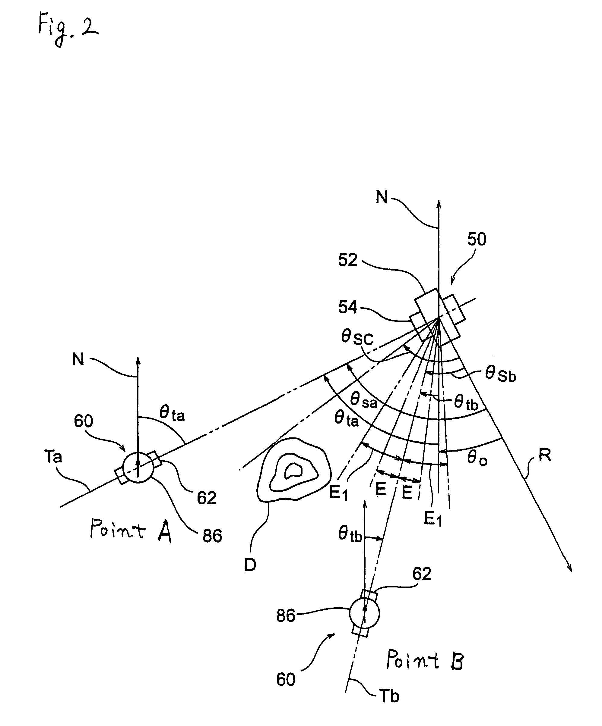
[0020]the present invention will now be described with reference to FIG. 1 to FIG. 3. FIG. 1 is a block diagram of the whole of a survey system in this embodiment. FIG. 2 is a view for explaining the principle of the survey system. FIG. 3 is a flowchart for explaining the operation of the body of a surveying instrument in the survey system.

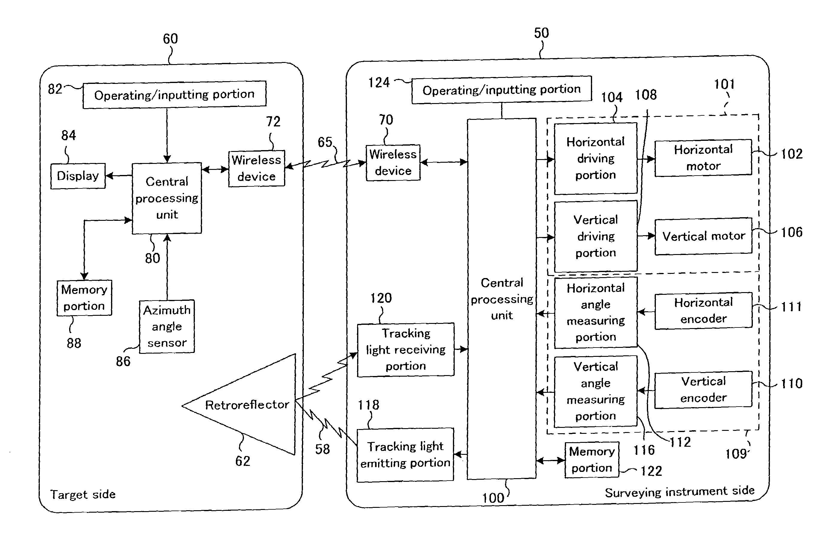
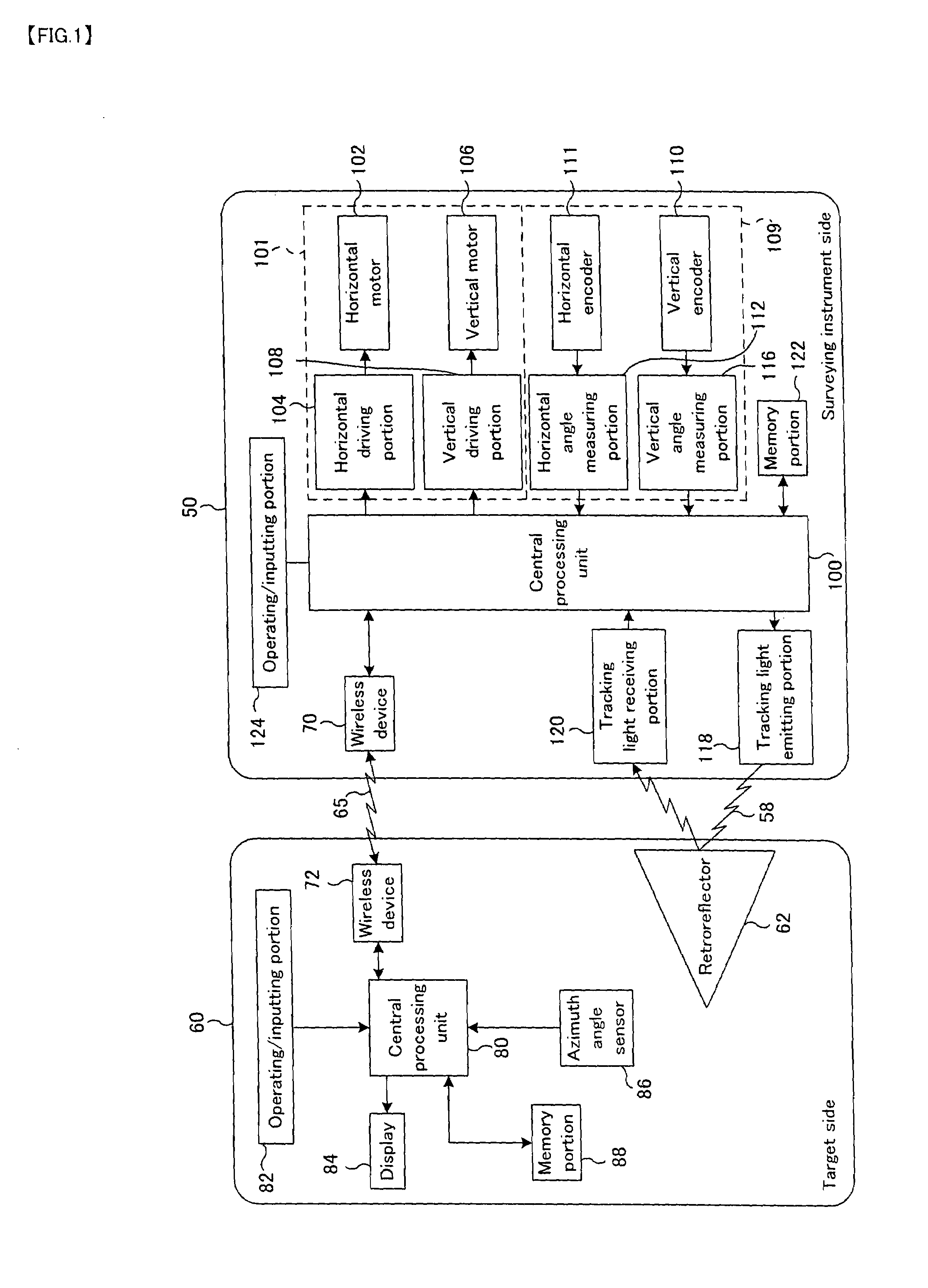
[0021]Referring first to the block diagram of FIG. 1, a description will be given of the respective internal structures of a surveying instrument 50 and a target 60 that constitute the survey system.

[0022]The surveying instrument 50 includes a driving portion 101 that directs a collimation telescope 54 (see FIG. 2) toward a reflecting prism (retroreflector) 62, a measuring portion 109 that measures a horizontal angle and a vertical angle of the collimation telescope 54, a tracking light emitting portion 118 that emits tracking light 58 toward the reflecting prism 62, a tracking light receiver 120 that receives the tracking light 58 reflected by th...

second embodiment

[0062][FIG. 4] Flowchart for explaining the operation of the survey system according to the present invention.

DESCRIPTION OF THE SYMBOLS

[0063]50 Surveying instrument[0064]52 Instrument body[0065]60 Target[0066]62 Retroreflector (reflecting prism, target)[0067]80, 100 Central processing unit[0068]86 Direction angle sensor[0069]112 Horizontal angle measuring portion (angle measuring means)[0070]θo Angular difference between surveying-instrument direction angle and target direction angle[0071]θta, θtb Surveying-instrument direction angle[0072]θsa, θsb, θsc Target direction angle


PUM


Abstract

[Problem] In a surveying instrument that automatically tracks or collimates a target, the target that is moved to a measurement point and is placed there can be found in the shortest possible time.[Solution Means] In a survey system made up of a target (60) and a surveying instrument (50) that automatically tracks or collimates the target, the target is provided with a direction angle sensor (86) that measures a surveying-instrument direction angle (θta, θtb) obtained when the target is directed toward the surveying instrument, whereas the surveying instrument is provided with a horizontal angle measuring portion that measures a target direction angle (θsa, θsb, θsc) indicating the direction of the target. An estimated target direction angle (θsb) is calculated from an angular difference (θo) between the surveying-instrument direction angle (θta) and the target direction angle (θsa) obtained at the last measurement and from the surveying-instrument direction angle (θtb) obtained at the present measurement. The instrument body (52) is directed in the direction of the estimated target direction angle.

Description

TECHNICAL FIELD[0001]The present invention relates to a surveying instrument that can automatically track a target and can automatically collimate the target.BACKGROUND ART[0002]In order to measure the position of a survey point or the like by using a conventional surveying instrument such as a total station (electric distance / angle meter), it was necessary to collimate a target placed at the survey point. In recent years, a surveying instrument having an automatic collimator has appeared on the market, in order to reduce the labor of an operator collimating a target. The surveying instrument having such an automatic collimator has come to include a remote control device so that a survey can be performed by a single operator. However, the surveying instrument provided with the automatic collimator has a conventional problem in the fact that a collimation telescope must scan a wide range in order to set the target within a narrow visual field of the telescope, and hence much time is ...

Claims


Application Information

Patent Timeline
Patent Type & Authority Patents(United States)
IPC IPC(8): G01B11/26
CPCG01C15/00
Inventor YASUTOMI, SATOSHICHIBA, MINORUNISHITA, NOBUYUKI
Owner KK TOPCON
Why Eureka
Try Eureka