Unlock instant, AI-driven research and patent intelligence for your innovation.

Node position measuring system

a position measurement and node technology, applied in the field of position measurement method, can solve the problems of difficult to miniaturize the node and achieve low power consumption, the method can only be used outdoors to receive a radio wave from the satellite, and the difficulty of miniaturizing the node and achieving low power consumption, so as to simplify the configuration of the base station

Inactive Publication Date: 2008-01-22
HITACHI LTD
View PDF23 Cites 5 Cited by
  • Summary
  • Abstract
  • Description
  • Claims
  • Application Information

AI Technical Summary

Benefits of technology

The invention provides a system for measuring the position of a node using a reference station and multiple base stations. The reference station receives the positioning signal and transmits a reference signal afterward. The base stations receive the positioning signal and the reference signal, measure the time it takes for the signals to pass through, and communicate this information to a server. The server calculates the position of the node based on the time information it receives. This system simplifies the configuration of the base station as it does not require an additional receiver for the positioning signal. Additionally, the system can measure the position of the node indoors without the need for many receiving stations.

Problems solved by technology

In the method in which the signal from the satellite such as a GPS is used, a special receiver or antenna is necessary, making it difficult to miniaturize the node and to achieve low power consumption.
This method can only be used outdoors to receive a radio wave from the satellite.
Besides, the node needs to have a receiver, making it difficult to miniaturize the node and to achieve lower power consumption.

Method used


Image

  • Node position measuring system
  • Node position measuring system
  • Node position measuring system

Examples


first embodiment

[0027]FIG. 1 is a block diagram showing a configuration of a positioning system according to a first embodiment of this invention.

[0028]The positioning system includes a node 01, a reference station 02, an access point (AP) 03, and a server 04.

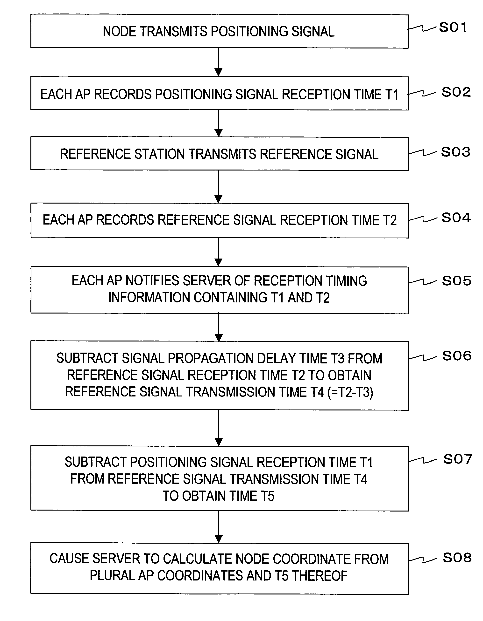
[0029]The node 01 transmits a radio packet (positioning signal) 05 for measuring a position. The reference station 02 receives the positioning signal 05 from the node 01, and then transmits a radio packet (reference signal) 06 to establish a reference time. The access point 03 receives the positioning signal 05 transmitted from the node 01 and the reference signal 06 transmitted from the reference station 02, and measures the times at which specific bit patterns of the received positioning signal 05 and of the received reference signals 06 are detected. The access point 03 transmits reception timing information 07 containing the measured times of detection of the specific bit patterns to the server 04 through a network 08. The network 08 may b...

second embodiment

[0093]According to the second embodiment of this invention, an access point for transmitting a reference signal 06 is used.

[0094]FIG. 10 is a block diagram showing a configuration of a positioning system according to the second embodiment of this invention.

[0095]The positioning system of the second embodiment is similar to that of the first embodiment shown in FIG. 1 except that the second embodiment includes an access point 10 in place of a reference station 02. Similar components are denoted by similar reference numerals, and description thereof will be omitted.

[0096]The access point 10 receives a positioning signal 05 from the node 01, transmits a reference signal 06 after the reception of the positioning signal 05 from the node 01, and measures a time of detection of a specific bit pattern of the received positioning signal 05 by a counter.

[0097]FIG. 11 is a block diagram showing a configuration of the access point 10 for transmitting the reference signal 06 according to the sec...


PUM


Abstract

A node position measuring system according to this invention includes a node, a reference station, base stations, a server that calculates a position of the node, and a network. The reference station includes a positioning signal reception module and a reference signal generation module that transmits a reference signal after the positioning signal reception module receives the positioning signal. Each of the base stations includes a signal reception module, a reception time measuring module that detects specific patterns from the positioning signal and the reference signal received by the signal reception module to measure a detection time, and a communication module that transmits time information, which is generated from the time measured by the reception time measuring module, to the server. The server includes a position calculation module that calculates the position of the node based on the time information transmitted from the base station.

Description

CLAIM OF PRIORITY[0001]The present application claims priority from Japanese patent application P2004-365939 filed on Dec. 17, 2005, the content of which is hereby incorporated by reference into this application.BACKGROUND OF THE INVENTION[0002]This invention relates to a position measuring method for measuring a position of a node having a radio transmitting function, a node position measuring system using the method, and an access point (AP) used as a base station in the node position measuring system.[0003]As a representative conventional node position measuring method, there has been available a method of measuring a position by using a signal from a satellite such as a GPS.[0004]As another node position measuring method, there has been available a method of receiving signals sent from several base stations by a node and calculating a position of the node based on a reception timing difference of the signals.[0005]Specifically, regarding a cellular telephone system, there has be...

Claims


Application Information

Patent Timeline
Patent Type & Authority Patents(United States)
IPC IPC(8): H04Q7/00G01S19/09G01S5/06G01S19/42H04W64/00H04W84/10H04W88/08
CPCG01S5/021G01S5/06
Inventor MIZUGAKI, KENICHIFUJIWARA, RYOSUKE
Owner HITACHI LTD