Bottom-lighting module

a technology of bottom-lighting modules and bottom-lighting components, which is applied in the direction of lighting safety devices, lighting and heating devices, instruments, etc., can solve the problems of reducing the life of many kinds of internal elements within the lcd product, reducing the life of many kinds of internal elements, and reducing the light weight and size, so as to achieve the effect of high heat sink ability

Active Publication Date: 2008-01-29
AU OPTRONICS CORP
View PDF3 Cites 9 Cited by
  • Summary
  • Abstract
  • Description
  • Claims
  • Application Information

AI Technical Summary

Benefits of technology

[0009]An objective of the present invention is to provide a bottom-lighting module with high heat sink ability.
[0010]Another objective of the present invention is to provide a bottom-lighting module having a maintaining display quality during a long operated duration.
[0011]Another objective of the present invention is to elongate life time of the internal elements of the bottom-lighting module.
[0012]The provided bottom-lighting module comprises a bezel, a protrusion and at least one lamp. The bezel has at least one aperture with a first circumference and a second circumference. The bezel comprises a main body and at least one inclined wall extending upward from an edge of the main body. The protrusion is formed on the outer side of the bezel corresponding to the at least one aperture. Part of the circumference of the protrusion corresponds to the first circumference of the at least one aperture. At least one lamp is disposed on the main body of the bezel. By these, an air-convecting tunnel, which is constructed by the second circumference, the protrusion, the first circumference and the second aperture, is capable of removing the heat within the bottom-lighting module with a remarkable efficiency.

Problems solved by technology

LCD television with its light weight and reduced size, especially the thickness, are having huge competition with traditional television.
This not only affects the function of LCD panel 12, causing the deterioration of display quality (i.e. some part of the displayed image turns out blurry and smudgy), but it could even decrease the life time of many kinds of internal element within the LCD product.

Method used


Image

  • Bottom-lighting module
  • Bottom-lighting module
  • Bottom-lighting module

Examples


Embodiment Construction

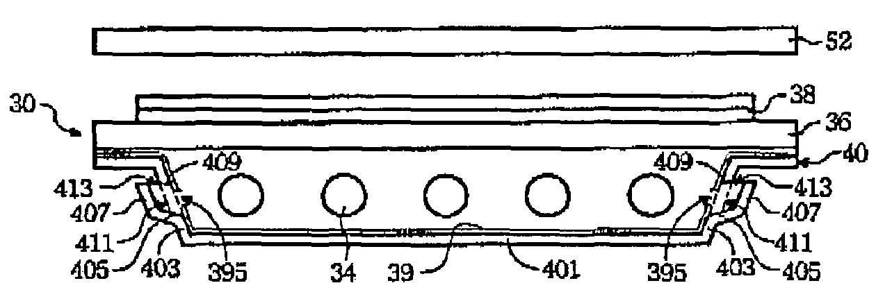
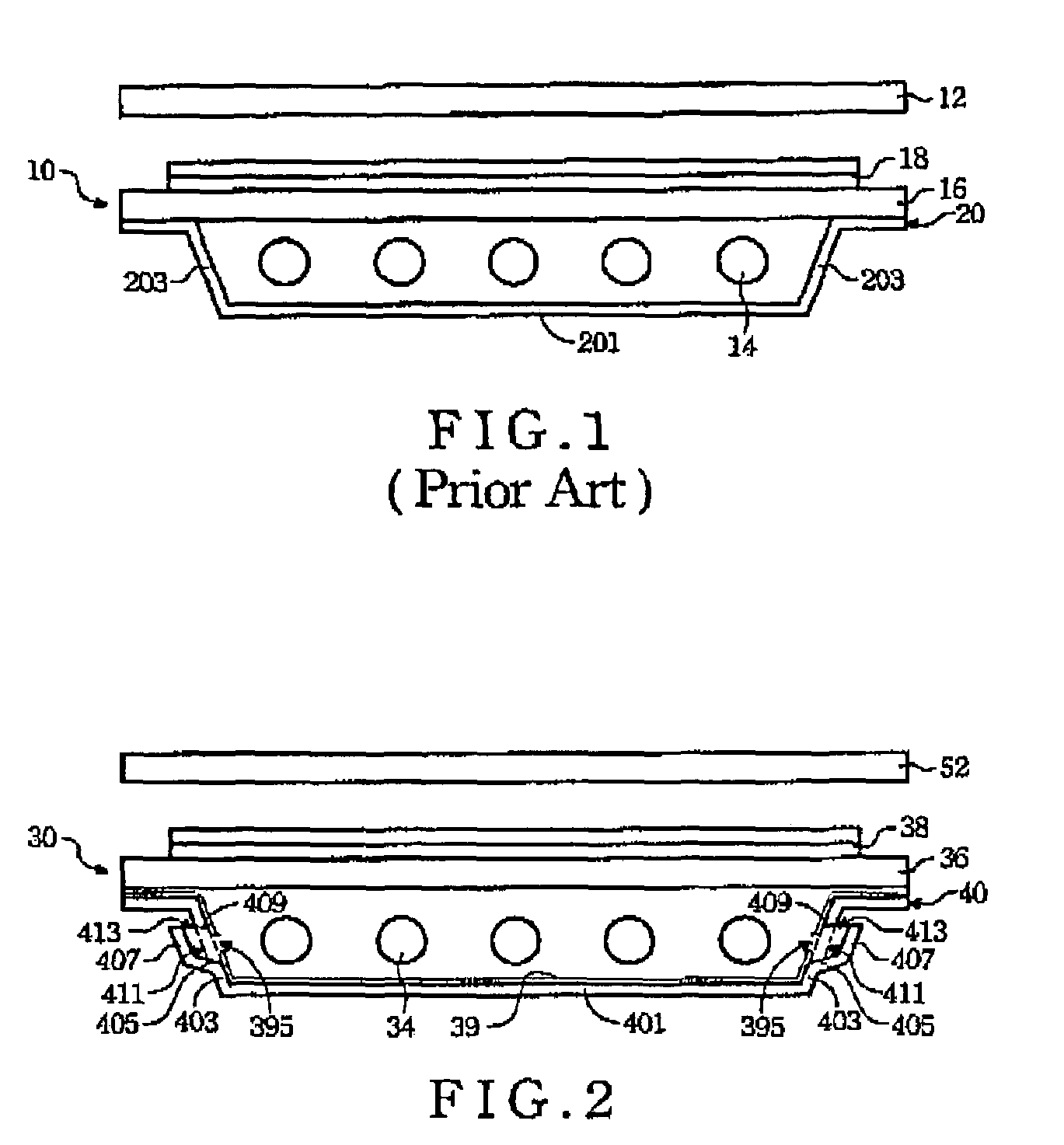
[0024]Referring to FIG. 2, it is a cross-section view of the present bottom-lighting module. While being employed in a display product, the bottom-lighting module 30 is disposed right underneath a display panel 52, such as a liquid crystal panel.

[0025]In bottom-lighting module 30, light is provided by the plurality of lamp 34, which is arranged horizontally to each other and located underneath the panel 52. The diffuser plate 36, located in between the plurality of lamp 34 and the panel 52, is needed for diffusing the light coming from beneath, so as to provide a more evenly distributed light to the panel 52. Above the diffuser plate 56, a plurality of optical film 38, such as a lower diffuser film, a lower brightness enhancement film, a upper brightness enhancement film and a upper diffuser film, is disposed to increase the overall light evenness and brightness of the bottom-lighting module 30. The disposed order and the selected type of mentioned plurality of optical film 38 are v...


PUM


Abstract

The provided bottom-lighting module comprises a bezel, a protrusion and at least one lamp. The bezel has at least one aperture with a first circumference and a second circumference. The bezel comprises a main body and at least one inclined wall extending upward from an edge of the main body. The protrusion is formed on the outer side of the bezel corresponding to the at least one aperture. Part of the circumference of the protrusion corresponds to the first circumference of the at least one aperture. At least one lamp is disposed on the main body of the bezel.

Description

BACKGROUND OF THE INVENTION[0001](1) Field of the Invention[0002]The present invention generally relates to a bottom-lighting module, which provides backlight source to a display panel, and particularly relates to a bottom-lighting module with excellent heat sink ability.[0003](2) Description of the Prior Art[0004]A Liquid Crystal Display (LCD) has been widely applied in notebook laptop, mobile phone, digital camera, video camera, PDA and other portable digital electronically products. Other than these small-sized portable products, the LCD inventing technology within large-sized products has been improved in great deal as well. For instance, desktop LCD monitor is replacing the traditional Cathode Ray Tube (CRT) monitor. LCD television with its light weight and reduced size, especially the thickness, are having huge competition with traditional television. A panel, or a liquid crystal panel, is an essential unit of the whole LCD. The panel itself does not generates light but modula...

Claims


Application Information

Patent Timeline
Patent Type & Authority Patents(United States)
IPC IPC(8): G01D11/28
CPCG02F1/133604G02F1/133608G06F1/20
Inventor LAI, CHING-KUN
Owner AU OPTRONICS CORP
Why Eureka
Try Eureka