Damper cooled turbine blade

a turbine blade and turbine blade technology, applied in the direction of machines/engines, liquid fuel engines, other chemical processes, etc., can solve the problems of turbine rotor blade cooling is particularly problematic, turbine rotor blade cooling is subject to centrifugal forces,

Inactive Publication Date: 2008-01-29
GENERAL ELECTRIC CO
View PDF9 Cites 54 Cited by
  • Summary
  • Abstract
  • Description
  • Claims
  • Application Information

AI Technical Summary

Problems solved by technology

The cooling circuits for the stator vanes and rotor blades vary in complexity, performance, and cost of manufacture in a multitude of permutations in a remarkably complex and crowded art due to the decades of development history in modern gas turbine engines.
Furthermore, a turbine rotor blade is subject to centrifugal forces when rotating with the perimeter of the supporting rotor disk.
Cooling of the turbine rotor blade platforms is particularly problematic because the platform should be as thin as practical to reduce centrifugal loads carried through the turbine blades, and correspondingly reduce centrifugal stress.
Thin platforms render impractical the introduction of internal cooling circuits therein in the myriad of configurations found for the relatively thicker turbine airfoils themselves.
And, film cooling of the turbine platforms themselves necessarily has limited effectiveness given the limited amount of cooling air that may be bled from the compressor, which correspondingly reduces overall efficiency of the engine.

Method used


Image

  • Damper cooled turbine blade
  • Damper cooled turbine blade
  • Damper cooled turbine blade

Examples


Embodiment Construction

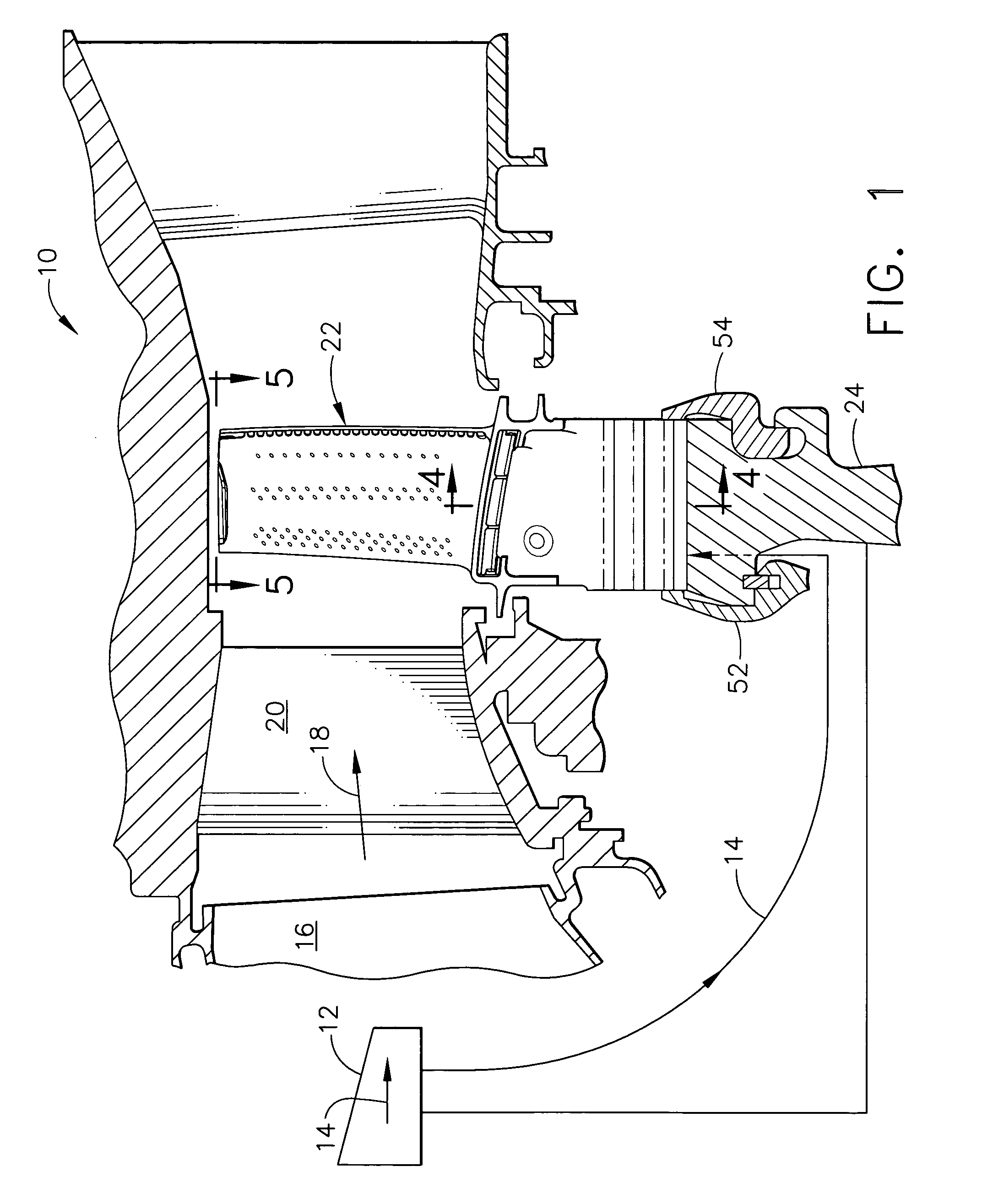
[0030]Illustrated in FIG. 1 is an axial sectional view of a portion of a turbofan gas turbine aircraft engine 10 which is axisymmetrical about a longitudinal or axial centerline axis.

[0031]The engine 10 includes a conventional multistage axial compressor 12 configured for pressurizing air 14 in succeeding stages thereof and providing the compressed air to a conventional annular combustor 16 shown in aft part. Fuel is added to the pressurized air in the combustor and ignited for generating hot combustion gases 18 which are discharged therefrom into a HPT.

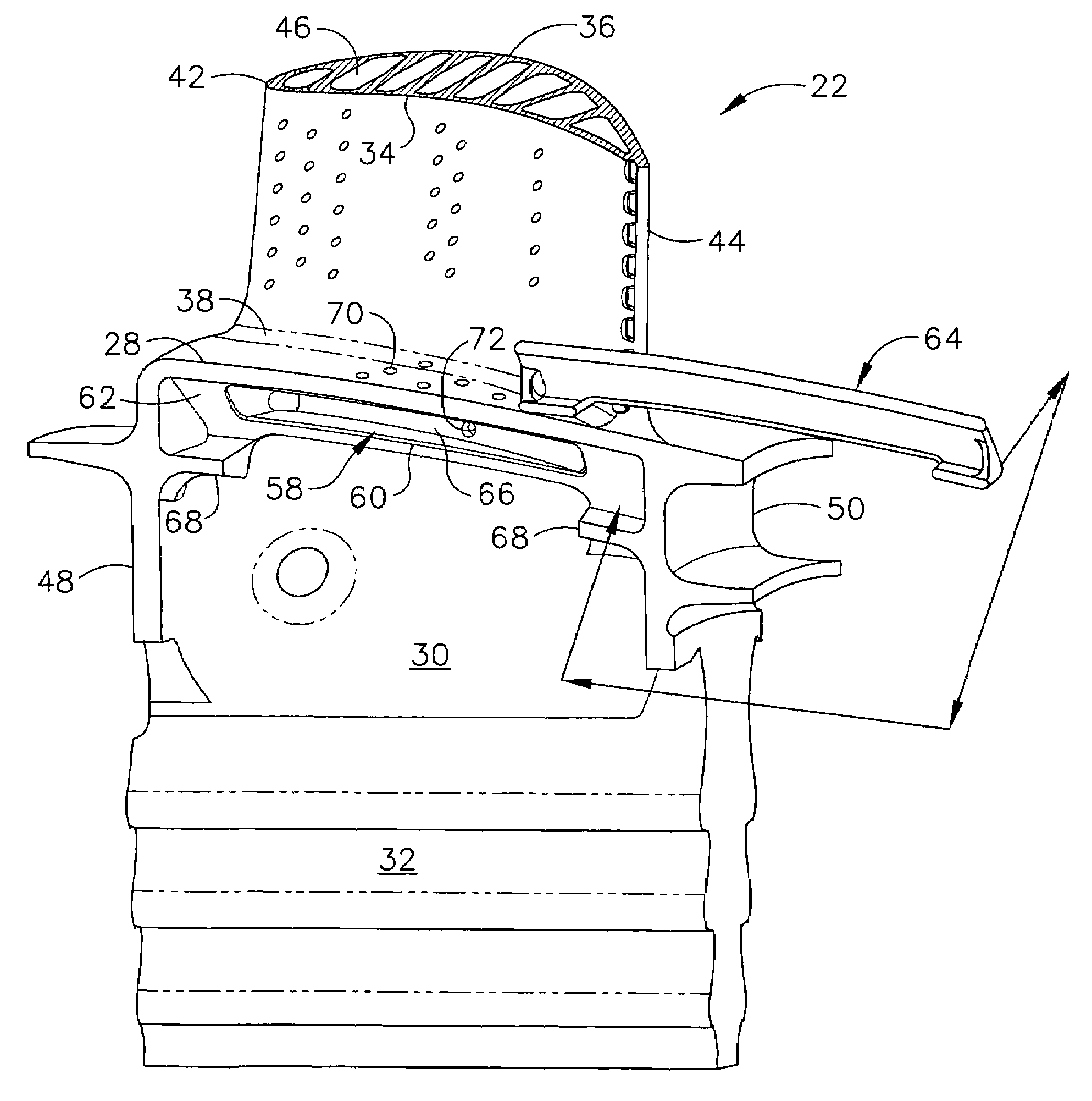
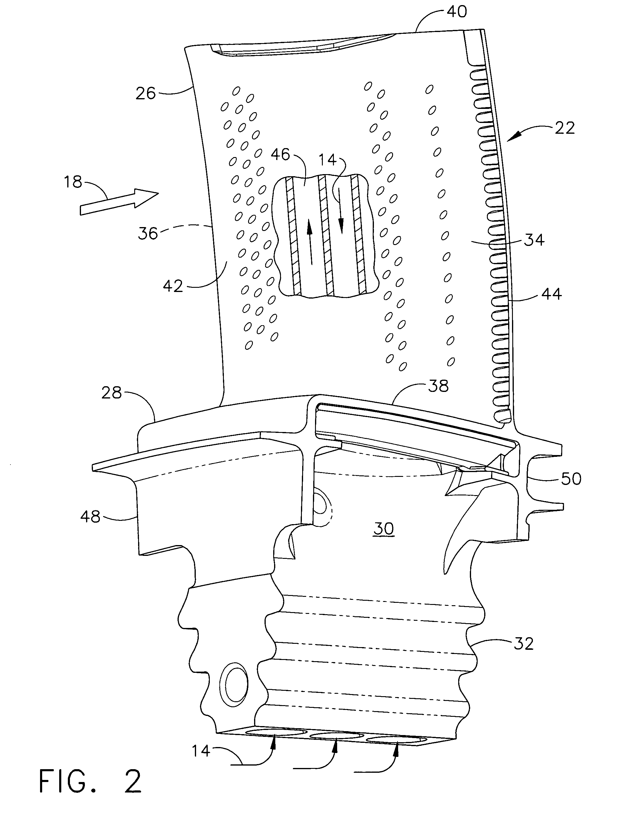
[0032]The HPT includes a first stage turbine nozzle having a row of hollow nozzle stator vanes 20 which channel the combustion gases aft through a row of first stage turbine rotor blades 22 conventionally mounted to a supporting rotor disk 24 shown in radially outer part. Energy is extracted by the turbine blades 22 which are connected by a drive shaft to the rotor of the compressor for powering the compressor during operation. The c...


PUM


Abstract

A turbine blade includes an airfoil, platform, shank, and dovetail integrally joined together. A cooling chamber is located under the platform and has a portal exposed outwardly from the shank. A damper seat surrounds the portal and is recessed under the platform for receiving a vibration damper to sealingly close the chamber across the portal.

Description

BACKGROUND OF THE INVENTION[0001]The present invention relates generally to gas turbine engines, and, more specifically, to turbine blade cooling therein.[0002]In a gas turbine engine, air is pressurized in a compressor and mixed with fuel in a combustor for generating hot combustion gases. Energy is extracted from the gases in a high pressure turbine (HPT) which powers the compressor, and in a low pressure turbine (LPT) which typically powers a fan in an aircraft turbofan engine application.[0003]The HPT includes a stator nozzle disposed at the outlet end of the combustor which first receives the hottest combustion gases therefrom. The nozzle includes a row of vanes which direct the combustion gases into a row of first stage turbine rotor blades mounted to the perimeter of a supporting rotor disk.[0004]The stator vanes and rotor blades have specifically configured airfoil profiles with generally concave pressure sides and generally convex opposite suction sides extending in radial ...

Claims


Application Information

Patent Timeline
Patent Type & Authority Patents(United States)
IPC IPC(8): F01D5/26
CPCF01D5/22F01D11/006Y02T50/671Y02T50/676F05D2250/292F05D2250/314F05D2240/81Y10S416/50Y02T50/60
Inventor LEE, CHING-PANGBRASSFIELD, STEVEN ROBERTSCHILLING, JAN CHRISTOPHER
Owner GENERAL ELECTRIC CO
Why Eureka
Try Eureka