Ground circuit impedance measurement

a ground circuit and impedance measurement technology, applied in the direction of impedence measurement, resistance/reactance/impedence, instruments, etc., can solve the problems of inability to take into account the resistance of numerous connections, inability to find existing products, and inability to calculate. to achieve the effect of automatically calculating

Inactive Publication Date: 2008-01-29
STITT THOMAS C
View PDF11 Cites 6 Cited by
  • Summary
  • Abstract
  • Description
  • Claims
  • Application Information

AI Technical Summary

Benefits of technology

[0014]The present invention provides novel apparatus and method for measuring ground circuit impedance including a ground circuit having an electrical current source, disconnecting electrical power by opening a main circuit breaker and a visible disconnect switch, a means of connecting power conductors, to the ground conductor at the end of the circuit, connecting an electrical alternating current source which passes current through the ground circuit, accurately measuring both the current introduced into the circuit and the resulting voltage drop produced in the ground circuit, and automatically calculating the ground impedance.
[0015]In one aspect, alligator clips are used to connect a current source to one phase wire and the ground wire. Another alligator clip is used to connect the voltage sensing device to another phase lead, which measures the voltage of that phase lead with respect to the ground wire connection. Since all phase leads are connected together at the far end of the circuit to be measured, the measures voltage is that which results from the current through the ground circuit. In applications where cable couplers are used, a special coupler may be used to conveniently connect all power conductors to the ground conductor. Power wires in the circuit to be measured serve as a means for carrying current and transmitting voltage data to determine directly the ground circuit impedance.
[0017]In applications which use cable couplers, inserting a special grounding coupler to provide a connection to ground off all power conductors may also be used to provide safety during inspection or troubleshooting.

Problems solved by technology

No existing products are available which measure ground impedance on certain type circuits.
What these calculations fail to take into consideration is the resistance of numerous connections such as high voltage couplers and bolted connections.
Although the Federal Coal Mine Health and Safety Act of 1969 mandated the grounding requirement years ago, there remains to this day no practical means of accurately determining ground circuit impedance.
These calculations fail to take into consideration the resistance of numerous connections such as high voltage couplers and bolted connections.

Method used


Image

  • Ground circuit impedance measurement
  • Ground circuit impedance measurement
  • Ground circuit impedance measurement

Examples


Embodiment Construction

[0024]The apparatus and method of the present invention provide novel ground circuit impedance measuring in medium and high voltage electrical power systems.

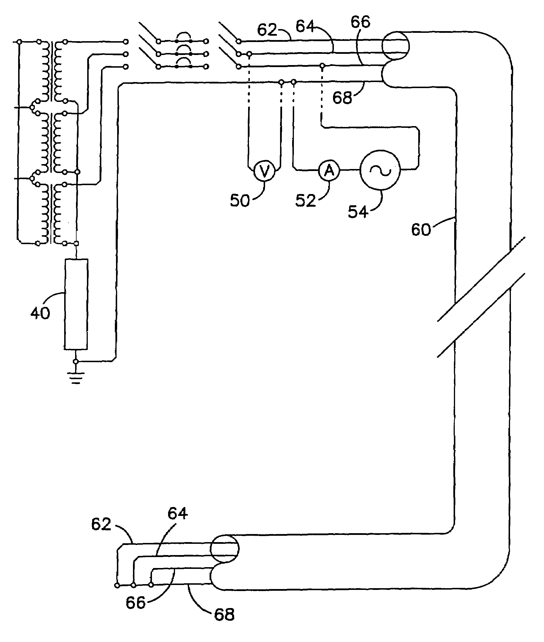
[0025]Specific embodiments of the apparatus and method of the present invention include means for circulating current through a grounding circuit and measuring the voltage drop across the ground circuit to determine circuit impedance. The novel device of this invention uses one of the power wires to carry current, and another power wire as means to measure voltage.

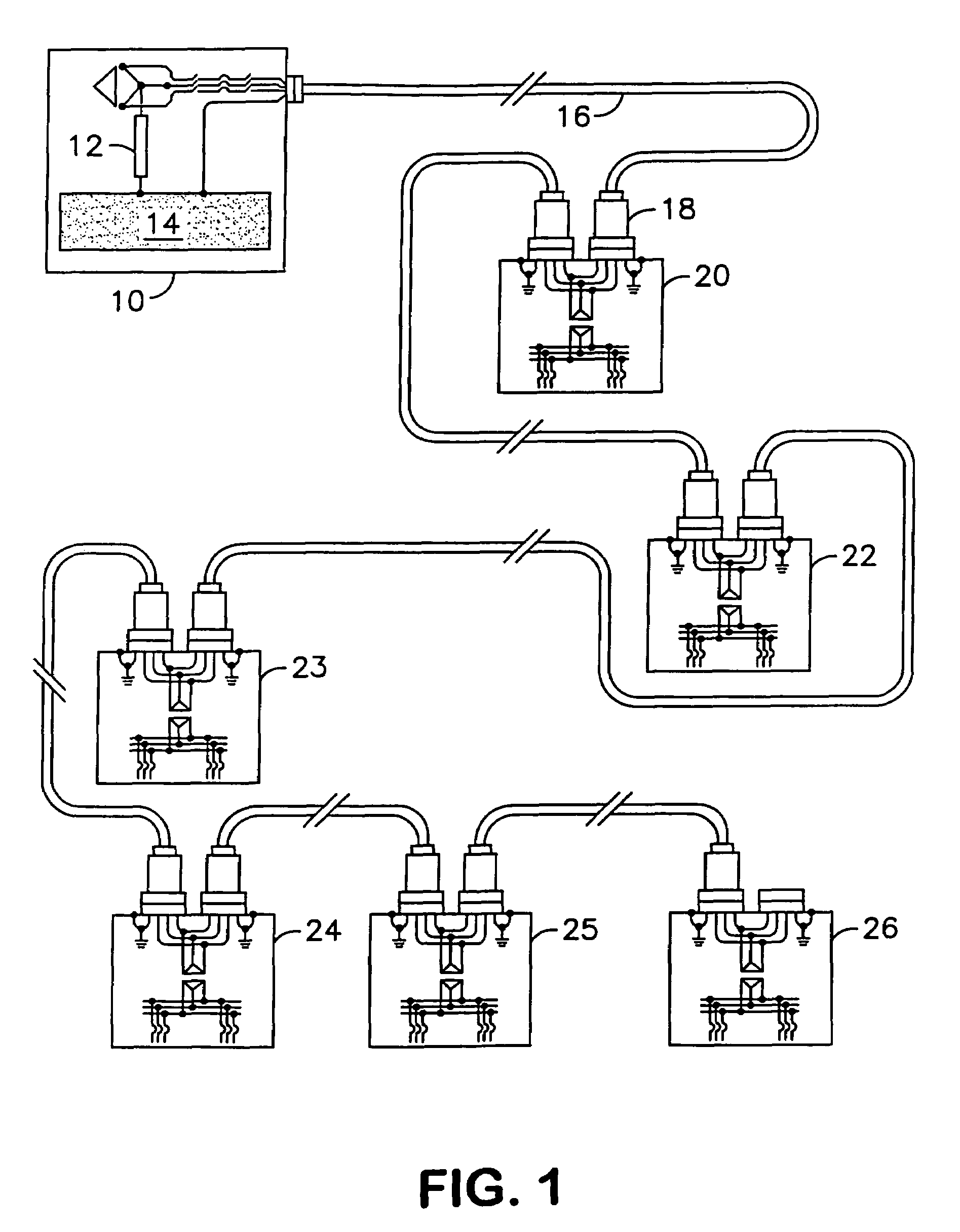
[0026]In one aspect, the novel apparatus and method of the present invention provide a means of measuring circuit impedance on very long cables. Some uses of the present invention provide for direct measurement of either ground circuit impedance or power circuit impedance.

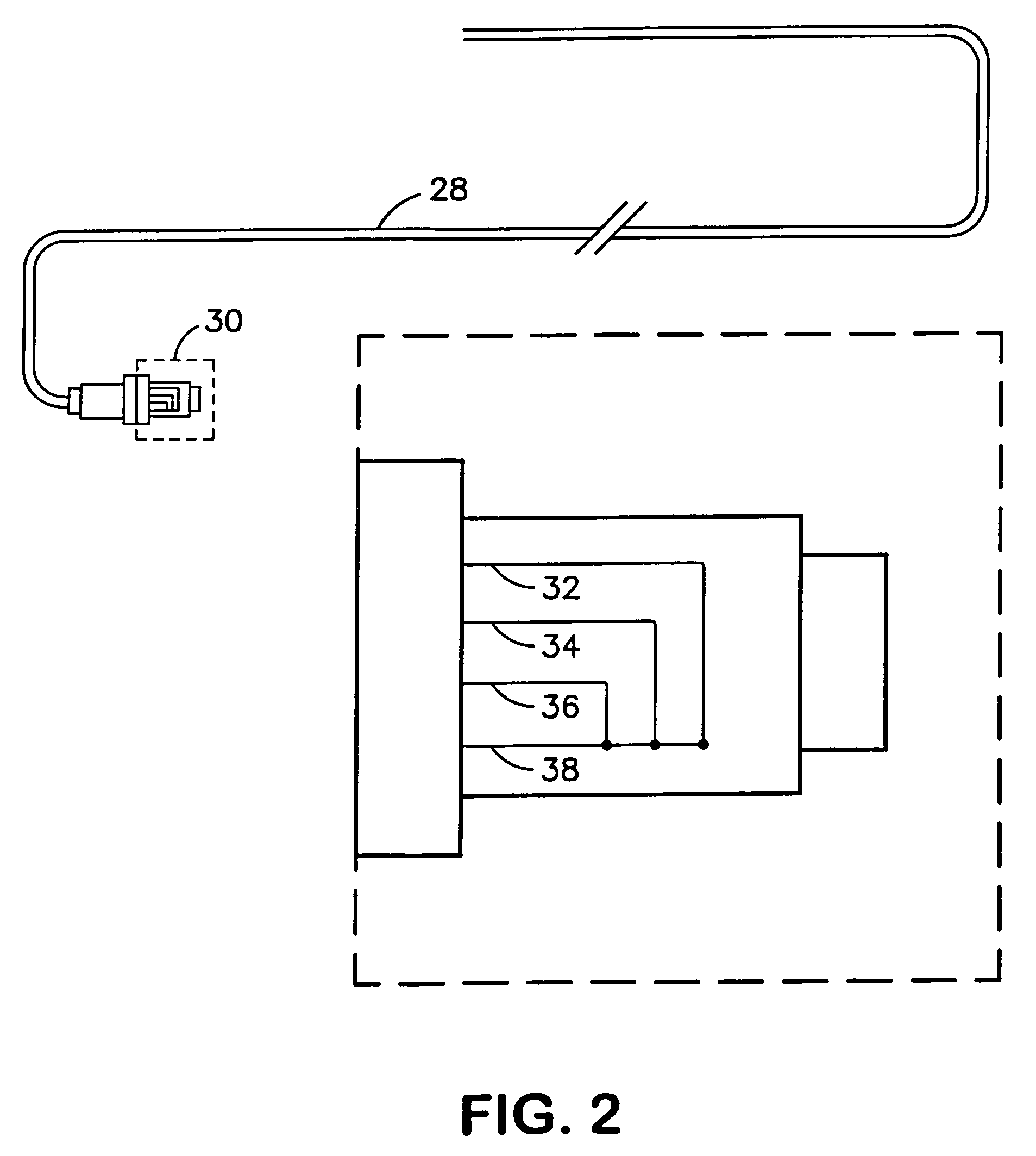
[0027]The apparatus and method of the high voltage coupler component, when used, of the present invention also include a preferred method of making the novel apparatus by inserting the coupler in the ...


PUM


Abstract

Novel apparatus and method accurately measure ground circuit impedance. A ground circuit and electrical current source adjusted to 25 amperes or less simulate a ground fault. Ground impedance is determined by dividing voltage drop by amperage to determine impedance directly. In one aspect, impedance is determined and displayed automatically. Power wires of the circuit being measured serve as a means for transmitting voltage and current data. The cable itself serves as a current-carrying and voltage-transmitting conduit to determine directly the circuit impedance. The novel ground circuit impedance device and method measure impedance in underground mine power systems connecting to an outside electrical power substation outside the mine and using portable transformers in the mine. The novel ground circuit impedance device and method also measure impedance in above-ground applications involving very long electrical power circuits such as those used to supply power to long conveyors and other electrical power equipment found in Metal / Non-Metal mines, including limestone quarries, sand and gravel operations, and other surface mines. In one aspect, ground circuit impedance is measured automatically in cables over 1 mile long.

Description

[0001]This application is a Continuation-In-Part of U.S. patent application U.S. Ser. No. 10 / 640,596 filed Aug. 13, 2003, which is a Continuation-In-Part of U.S. patent application U.S. Ser. No. 60 / 403,825 filed Aug. 14, 2002.BACKGROUND OF THE INVENTION[0002]1. Technical Field[0003]This invention relates to impedance measurement apparatus and method. In one aspect, this invention relates to the design, construction, and installation of ground circuit impedance measurement apparatus in an underground coal mine. In one aspect, this invention relates to the design, construction, and installation of ground circuit impedance measurement apparatus in other industrial applications where accurate measurement of ground circuit impedance is required.[0004]2. Background[0005]In underground coal mines, as well as other industrial applications, medium voltage and high voltage electrical power equipment is commonly used. As an example, in coal mines, the portable, high voltage electrical power eq...

Claims


Application Information

Patent Timeline
Patent Type & Authority Patents(United States)
IPC IPC(8): G01R31/08G01R27/18G01R31/14
CPCG01R27/18G01R27/205
Inventor STITT, THOMAS C.
Owner STITT THOMAS C
Why Eureka
Try Eureka