Electronic device hinge structure

a technology of electronic devices and hinges, which is applied in the direction of portable computer details, electric apparatus casings/cabinets/drawers, instruments, etc., can solve the problems of reducing the structural strength of the display unit, reducing the thickness of the display unit housing, and reducing the thickness of the display unit. , to achieve the effect of preventing damage or scratches of the housing, reducing the manufacturing cost of the electronic device, and preventing the damage or scratching of the housing

Inactive Publication Date: 2008-01-29
INVENTEC CORP
View PDF9 Cites 15 Cited by
  • Summary
  • Abstract
  • Description
  • Claims
  • Application Information

AI Technical Summary

Benefits of technology

[0009]In light of the drawbacks in the prior art, a primary objective of the present invention is to provide an electronic device hinge structure, which can prevent damage or scratches of a housing caused by force-induced deformation of a display unit of the electronic device.
[0010]Another objective of the present invention is to provide an electronic device hinge structure, which can keep the electronic device light and portable.
[0011]A further objective of the present invention is to provide an electronic device hinge structure without increasing the fabrication cost of the electronic device.
[0012]To achieve the aforementioned and other objectives, the present invention proposes an electronic device hinge structure. The electronic device comprises a display unit and a base unit on which the display unit is pivoted. The hinge structure comprises at least one rotation shaft horizontally protruded on a side of the display unit, and having a bearing portion formed on at least one end thereof; and at least one bearing member formed on the base unit at a position corresponding to the rotation shaft, and having a supporting portion formed thereon at a position corresponding to the bearing portion, such that the bearing portion correspondingly abuts against and is supported on the supporting portion so as to prevent a housing of the electronic device from being scratched or damaged by bezels on the display unit if being deformed by external force.
[0013]The hinge structure is applied to the electronic device, such as a portable computer. When the display unit is exerted with external force, for example being pressed by a user's arms, and becomes deformed, the supporting portion located at a side of the base unit supports the bearing portion of the rotation shaft on the display unit, so as to provide better pivot strength and better structural strength for the display unit to prevent deformation of the display unit by force. This further avoids scratches or damages of a housing at a hinge portion between the display unit and the base unit caused by the bezels of the display unit if being deformed, and thus maintains the appearance of the electronic device such as portable computer intact.
[0014]Moreover, the hinge structure in the prevent invention for reinforcing the connection between the display unit and the base unit is to form the supporting portion on the bearing member of the base unit and form the bearing portion on the rotation shaft of the display unit. This does not alter the original structural design of the electronic device, but simply adds components to the original structure. Such arrangement is simple to implement and easy to realize. Further, there is no need to change housing materials of the display unit and the base unit or use an expensive material such as a coating material with enhanced abrasion resistance. Therefore, the fabrication cost can be reduced.

Problems solved by technology

However, such thickness and gap do not facilitate the requirements of light weight and thin profile for an electronic device.
However, such reduction in the thickness of the display unit housing is limited and causes degradation of structural strength of the display unit.
As a result, under a condition of being exerted with force, the display unit may easily be bent and deformed, and thus bezels on the display unit at a hinge portion being pivoted on the base unit would scratch and damage a surface of the hinge portion due to undesirable contact therebetween, thereby impairing the appearance of the electronic device.
However, using the magnesium-aluminum housing or the abrasion resistant coating requires the expensive magnesium-aluminum alloy material and fabrication processes, or needs the expensive coating additive, such that the fabrication cost would be significantly increased.

Method used


Image

  • Electronic device hinge structure
  • Electronic device hinge structure
  • Electronic device hinge structure

Examples


Embodiment Construction

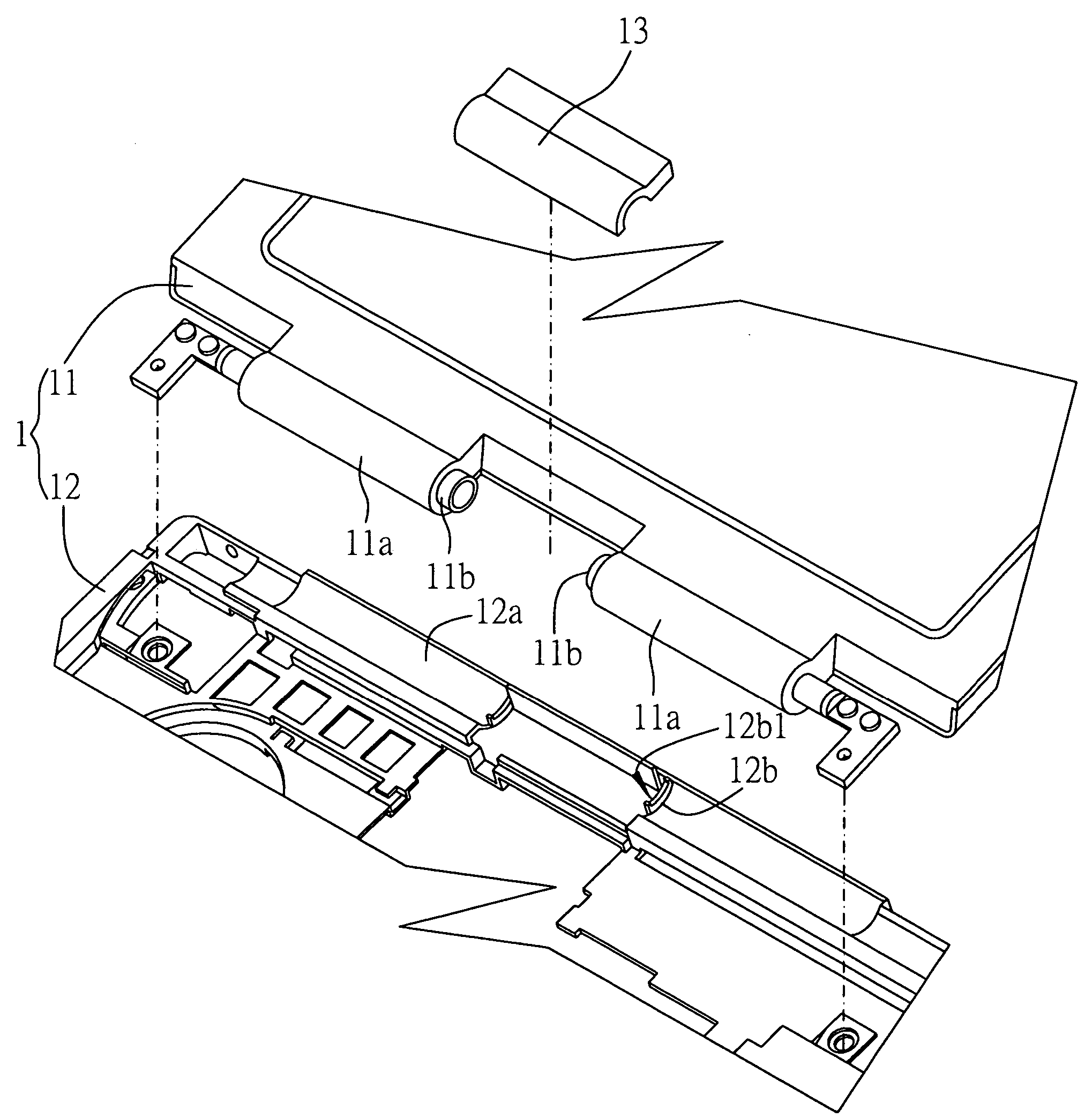
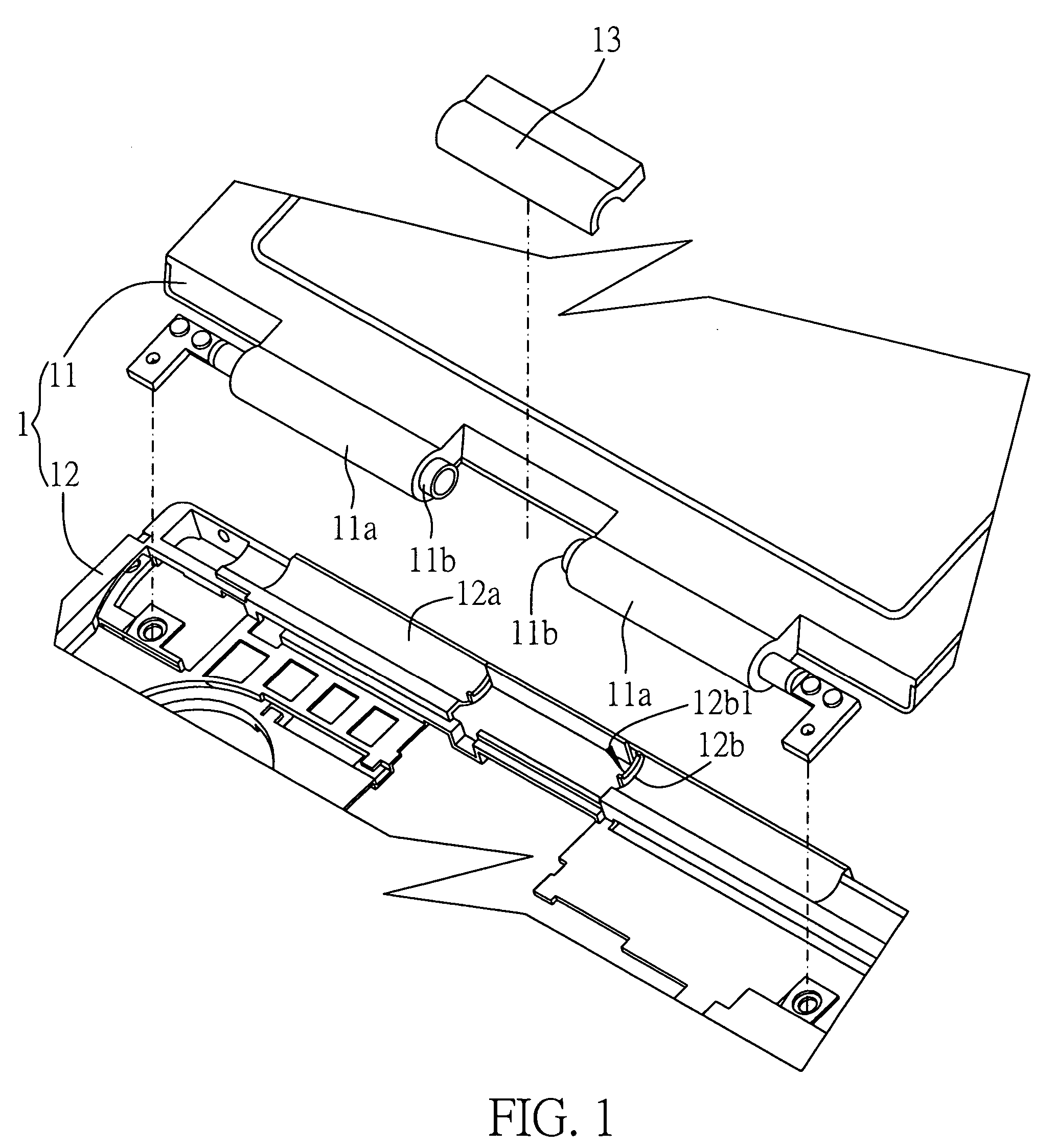
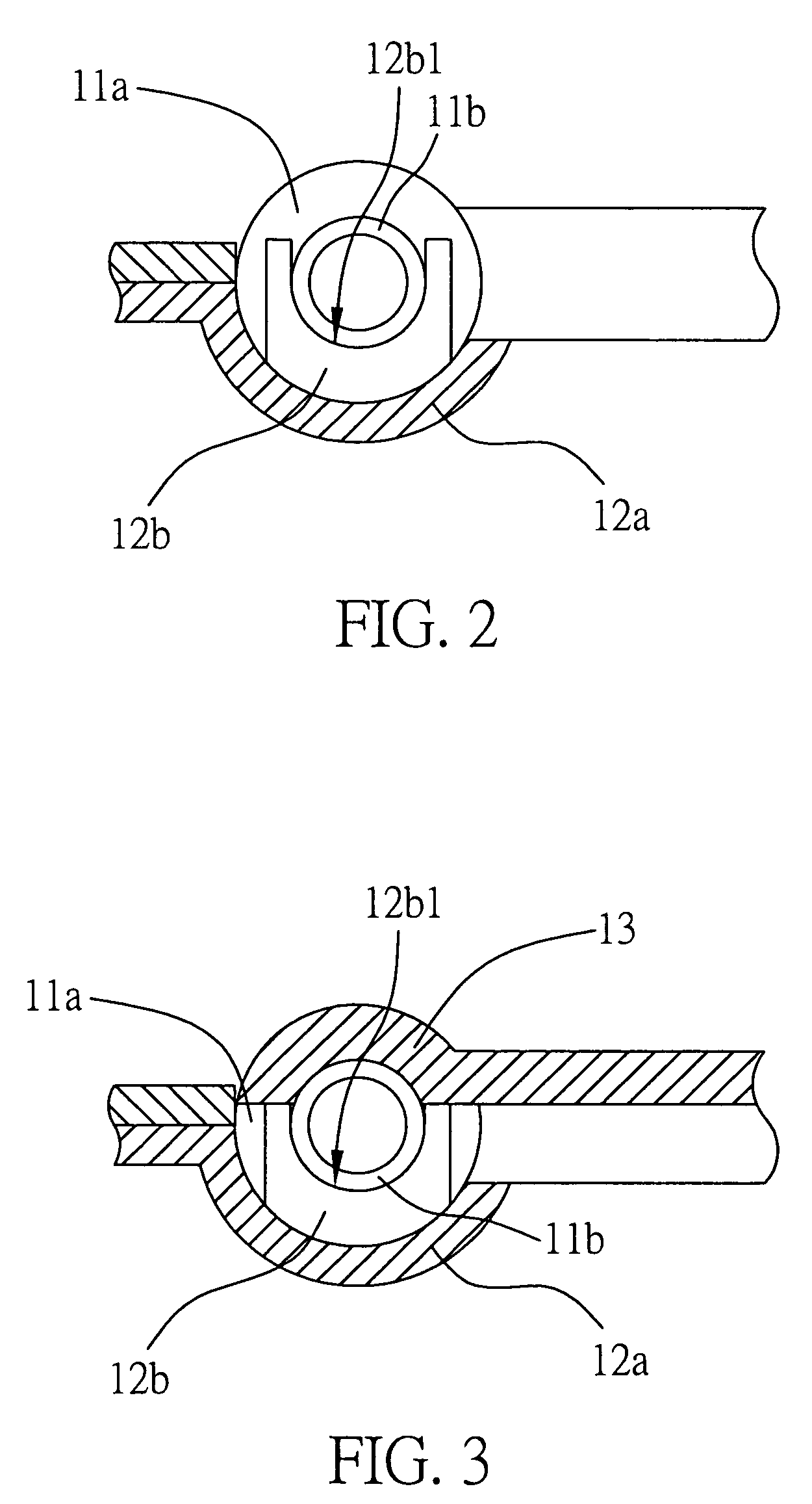
[0019]FIG. 1 is a perspective and exploded view of an electronic device hinge structure according to the present invention. The hinge structure is primarily applied to an electronic device 1 such as a portable computer. The electronic device 1 comprises a display unit 11 and a base unit 12 on which the display unit 11 is pivoted. The hinge structure comprises at least one rotation shaft 11a horizontally protruded on a side of the display unit 11 and having a columnar shape, wherein a bearing portion 11b is formed on at least one end of the rotation shaft 11a and has a round disc shape, and the rotation shaft 11a has a larger external diameter than that of the bearing portion 11b; at least one bearing member 12a formed on a side of the base unit 12 at a position corresponding to the rotation shaft 11a, and having a supporting portion 12b formed thereon at a position corresponding to the bearing portion 11b, wherein the supporting portion 12b is shaped as a rib plate having an arc rec...


PUM


Abstract

An electronic device hinge structure includes at least one rotation shaft horizontally protruded on a side of a display unit of the electronic device and having a bearing portion formed on at least one end thereof; and at least one bearing member formed on a side of a base unit of the electronic device at a position corresponding to the rotation shaft on the display unit, and having a supporting portion formed thereon at a position corresponding to the bearing portion, such that the bearing portion correspondingly abuts against and is supported on the supporting portion so as to reinforce structural strength of the display unit and prevent scratches of a housing of the electronic device caused by bezels on the display unit if being deformed by external force.

Description

FIELD OF THE INVENTION[0001]This invention relates to electronic device hinge structures, and more particularly, to a hinge structure for mechanically and electrically coupling a display unit to a base unit of an electronic device.BACKGROUND OF THE INVENTION[0002]For a conventional electronic device, cold cathode fluorescent lamps (CCFLs) are provided on two sides of a liquid crystal display (LCD) of the electronic device, and the CCFLs have a longer irradiation distance, thereby making illumination of the LCD screen relatively dim. In recent years, there has been provided an electronic device with a wide LCD unit, wherein CCFLs are located underneath the LCD unit, and the LCD unit is pivoted on a side of a base unit of the electronic device, such that the CCFLs have a shorter irradiation distance to improve brightness and contrast of the screen.[0003]Currently, in the foregoing electronic device with CCFLs being provided underneath the display unit, the location of CCFLs correspond...

Claims


Application Information

Patent Timeline
Patent Type & Authority Patents(United States)
IPC IPC(8): G09G5/00H04B1/38
CPCG06F1/1616G06F1/1681Y10T16/52
Inventor LIN, TIEN-CHANGMIAO, XIN-JIE
Owner INVENTEC CORP
Why Eureka
Try Eureka