Laser-scanning microscope with collimator and/or pinhole optics

a collimator and optics technology, applied in the field of laser scanning microscopes, can solve the problems of frequent substantial mechanical adjustment paths

Inactive Publication Date: 2008-01-29
CARL ZEISS MICROSCOPY GMBH
View PDF24 Cites 24 Cited by
  • Summary
  • Abstract
  • Description
  • Claims
  • Application Information

AI Technical Summary

Problems solved by technology

But substantial mechanical adjustment paths often occur even within one channel.
This is caused by the mostly strong wavelength dependency of the chromatic distortion within the UV and IR ranges.

Method used


Image

  • Laser-scanning microscope with collimator and/or pinhole optics
  • Laser-scanning microscope with collimator and/or pinhole optics
  • Laser-scanning microscope with collimator and/or pinhole optics

Examples


embodiment example

6. Embodiment Example for Focal Distance f′=22 (Collimator Optics)

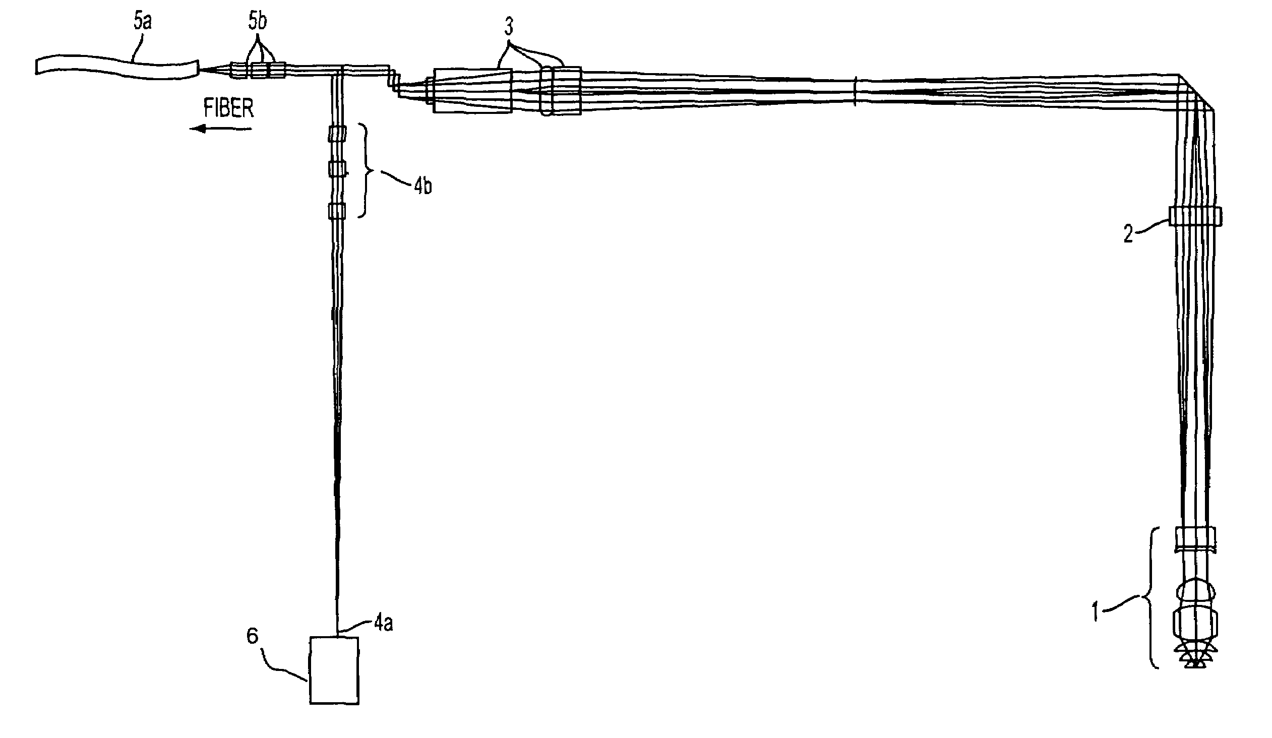
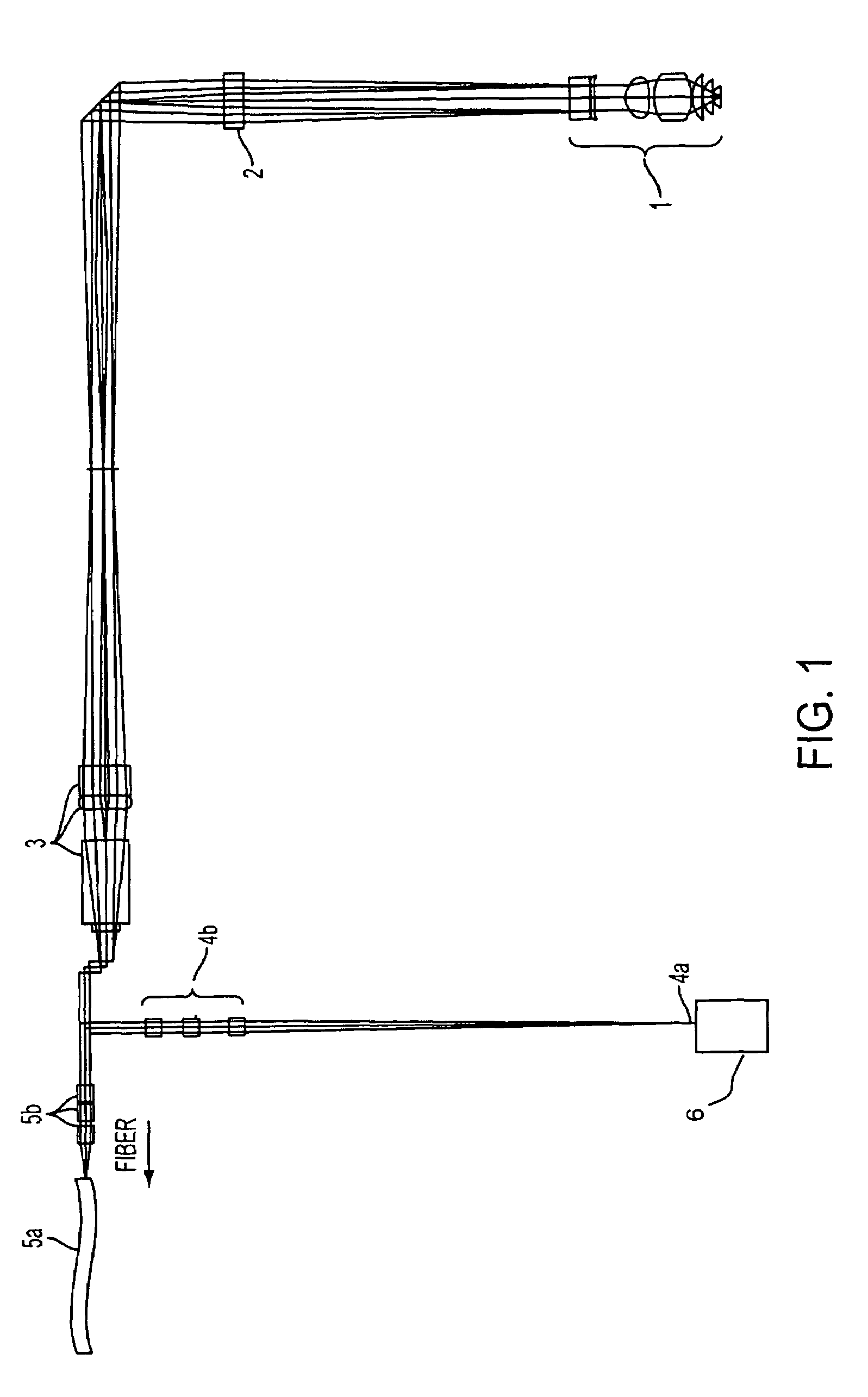
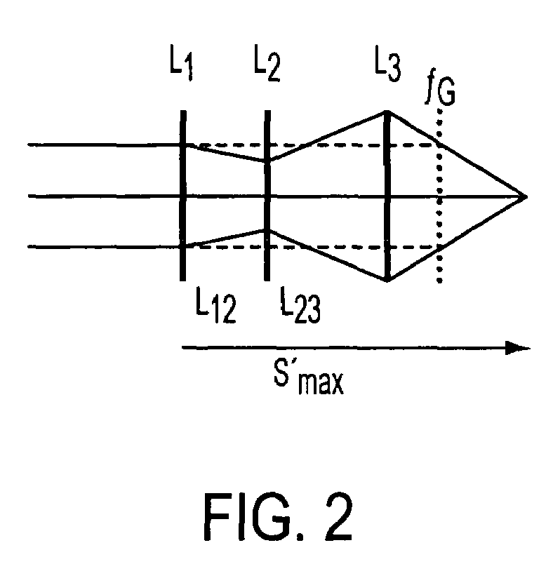
[0034]The collimator optics have the task of transferring the point source at the fiber output with a numeric aperture of about 0.07 into a parallel beam with a diameter of 3.2 mm in the infinite space in front of the scan objective lens. For this purpose, optics with a focal distance of 22 mm is required. It should further realize a partial compensation of the chromatic distortion of the objective lenses by means of rotation of the chromatic curve. The imaging of infinite into the fiber output can be performed as follows (where each lens group is replaced by a single lens):

[0035]

SequentialDistanceRadiusGlassLens focalRefractionnumber[mm][mm]Typelength f′index neνε1infinite 10.1N-FK516.41.4891479.52 3.6−34.03 1.7−11.2F2−11.61.6240841.04 3.6 23.25 3.7 7.3N-FK516.11.4891479.56 3.6 81.7714.3infinite

where νε is the Abbe number at a wavelength of 546.1 nm (the yellow-green Fraunhofer line “e” in mercury).

Distances:

d2: thic...


PUM


Abstract

Laser-scanning microscope with at least one detection radiation input, in which an aperture plate is installed in front of the detector, whereby optics with variable transmission lengths and a fixed focal distance is provided for focusing varying wavelengths of the detected light onto the aperture plate level at the detection radiation path, which realizes the imaging from the infinite space into an image level with a finite conjugate distance,
and/or
with at least one light source launched via an optical fiber, whereby collimator optics with a fixed focal distance, and a variable conjugate distance are down-streamed from the fiber output, which transfers the point source at the fiber output with a numerical aperture into a parallel beam in the infinite space in front of the scan-objective lens, whereby a wavelength-dependent, at least partial compensation of the chromatic distortion of the micro-objective lenses occurs by means of turning the chromatic curve for the illumination wavelength used.

Description

BACKGROUND OF THE INVENTION[0001]The laser-scanning microscope (LSM) represents a modern tool for observing smaller structures [1]. As with the traditional microscope, the object is initially imaged via the objective and tube lenses onto the intermediate image level. In a second imaging step of the LSM the confocal principle is realized on the excitation and detection sides. On the excitation side, the launching occurs by means of a punctiform fiber output via a collimator [2], or directly into the infinite space in front of the scanning objective lens, which is focused onto the intermediate image level of the traditional microscope alignment. For the detection the spectrally staggered fluorescent radiation originating from the objective is used, which falls onto a pinhole for detection via the scanning objective and pinhole optics after the intermediate image level. Excitation and detection channels are separated by means of color separators. With the aid of scanning mirrors, which...

Claims


Application Information

Patent Timeline
Patent Type & Authority Patents(United States)
IPC IPC(8): G02B21/06G02B27/12G02B21/00G02B21/02
CPCG02B21/0032G02B21/008
Inventor WINTEROT, JOHANNESGOELLES, MICHAEL
Owner CARL ZEISS MICROSCOPY GMBH
Why Eureka
Try Eureka