Method for producing a built shaft

a technology of built shafts and shafts, which is applied in the direction of manufacturing tools, couplings, machines/engines, etc., can solve the problems of relatively complex design of cams and may be manufactured only at a comparatively high cos

Inactive Publication Date: 2008-02-05
NEUMAYER TEKFOR HLDG GMBH
View PDF11 Cites 5 Cited by
  • Summary
  • Abstract
  • Description
  • Claims
  • Application Information

AI Technical Summary

Benefits of technology

[0009]The essential advantage of the present invention is that complex hydraulic widening operations on a hollow shaft, in particular a camshaft such as those required in the related art need not be performed because the diameter of the shaft is reduced elastically by stretching before pushing the cams and / or other components onto the shaft, so that it is readily possible to push said cams and / or components onto the shaft. Advantageously, no complex changes need be made on the cams and / or components themselves in the implementation of the method according to this invention.
is that complex hydraulic widening operations on a hollow shaft, in particular a camshaft such as those required in the related art need not be performed because the diameter of the shaft is reduced elastically by stretching before pushing the cams and / or other components onto the shaft, so that it is readily possible to push said cams and / or components onto the shaft. Advantageously, no complex changes need be made on the cams and / or components themselves in the implementation of the method according to this invention.

Problems solved by technology

Furthermore, the cams have a relatively complex design and therefore may be manufactured only at a comparatively high cost.

Method used


Image

  • Method for producing a built shaft
  • Method for producing a built shaft
  • Method for producing a built shaft

Examples


Embodiment Construction

[0015]Further scope of applicability of the present invention will become apparent from the detailed description given hereinafter. However, it should be understood that the detailed description and specific examples, while indicating preferred embodiments of the invention, are given by way of illustration only, since various changes and modifications within the spirit and scope of the invention will become apparent to those skilled in the art from this detailed description.

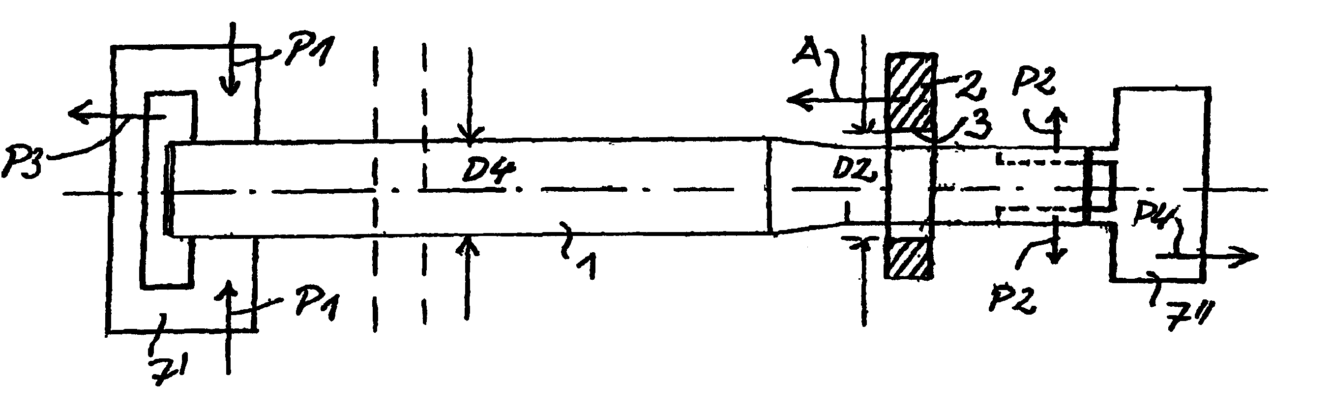
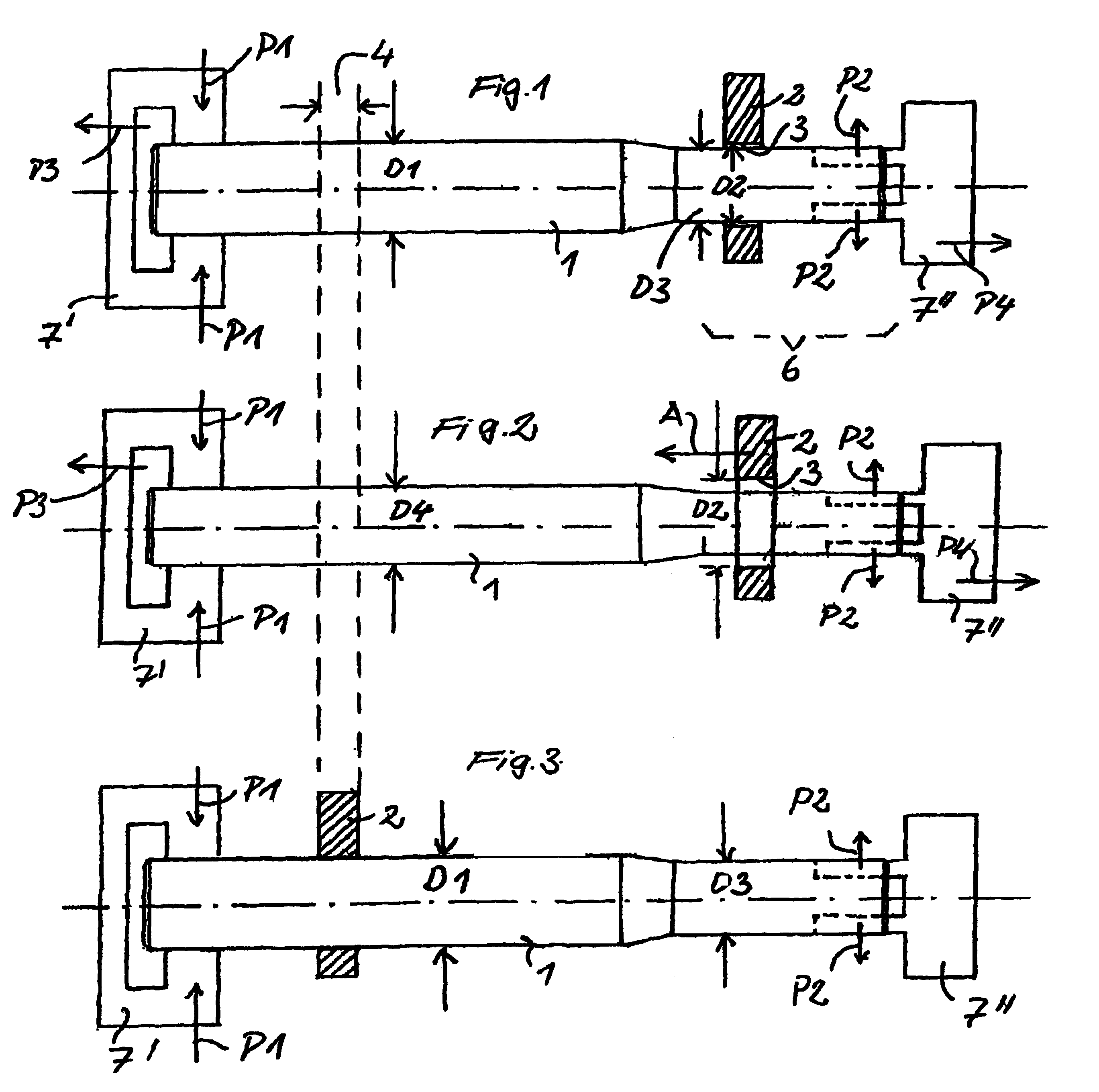
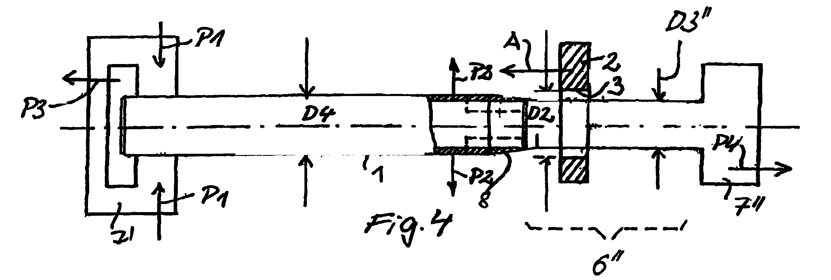
[0016]FIG. 1 shows a shaft, preferably designed as a hollow shaft, in particular a camshaft 1. A component to be mounted on the camshaft 1 may be, for example, a cam 2. The cam 2 has an inner opening 3 into which the camshaft 1 is inserted in the manner described below for mounting the cam 2 on the camshaft 1. The camshaft 1 has an outside diameter D1 at least at the mounting site 4 where the cam 2 is to be mounted. The inside diameter of the inner opening 3 of the cam 2 is labeled as D2.

[0017]A so-called threadi...


PUM

PropertyMeasurementUnit
diameteraaaaaaaaaa
forceaaaaaaaaaa
circumferenceaaaaaaaaaa

Abstract

A method of producing a built shaft in which at least one part, particularly a cam, is mounted on the shaft, particularly a camshaft, includes inserting the shaft into an opening of the part. Before mounting the part, the shaft is stretched by a stretching and tightening device such that an original diameter in the area of at least one fastening location is reduced to a stretched diameter. The part is slid onto the shaft and up to the fastening location. The stretching and tightening device is then loosened to enable the diameter of the shaft to enlarge once more towards its original diameter. The part is firmly fastened at the fastening location by an interference fit in both an axial and rotationally fixed manner.

Description

[0001]This is a nationalization of PCT / DE02 / 00083 filed Jan. 14, 2002 and published in German.BACKGROUND OF THE INVENTION[0002]1. Field of Invention[0003]This invention relates to a method of producing a worked shaft by stretching the shaft to reduce its diameter, moving a component onto the stretched shaft, and terminating the stretching so that the shaft regains some of its original diameter and secures the component to the shaft. In particular, this invention relates to a method of producing worked camshafts.[0004]2. Description of the Prior Art[0005]To attach cams or other components to a camshaft, which is hollow in a manner that has long-term stability, it is known that prefabricated cams or components may be pushed onto the camshaft and to widen them hydraulically in some locations so that the cams and / or components are secured in a torsionally fixed manner. The locally limited widening of the camshaft is relatively complex because special provisions are required (special pro...

Claims


Application Information

Patent Timeline
Patent Type & Authority Patents(United States)
IPC IPC(8): B21D53/84B21K1/12B23P11/02F01L1/047F16H53/02
CPCB21D53/845B23P11/02F01L1/047F16C3/023F16H53/025F16D1/0852B23P2700/02Y10T29/49293Y10T29/49838Y10T29/49874Y10T29/49863F16C2360/18
Inventor VOGEL, MANFRED
Owner NEUMAYER TEKFOR HLDG GMBH
Why Eureka
Try Eureka