Independent rear suspension

a rear suspension and independent technology, applied in the direction of suspension arms, pivoted suspension arms, transportation and packaging, etc., can solve the problems of reducing the space available for the feet of the third row passenger, the length of the lower control arms on the full frame vehicle is limited, and confusion

Active Publication Date: 2008-02-05
FORD GLOBAL TECH LLC
View PDF21 Cites 32 Cited by
  • Summary
  • Abstract
  • Description
  • Claims
  • Application Information

AI Technical Summary

Benefits of technology

[0020]One advantage that may be achieved by the invention, as summarized above, is that the foot well for a third row passenger seat may be enlarged due to less space being required forward of the axle for the suspension system components. Another advantage that may be achieved is that an independent rear suspension may be provided that may be readily tuned to provide desired ride and handling characteristics. Yet another advantage of the invention is that camber and toe-in adjustments may be performed with reduced confounding resulting from adjustment of either the camber or toe-in adjustment mechanisms.
[0021]In addition to the above advantages, other advantages are provided and other problems may be solved by applicants' invention as will be better understood in view of the attached drawings and following detailed description of the illustrated embodiment of the invention.

Problems solved by technology

The length of lower control arms on full frame vehicles are limited generally to the distance between the frame rails and the wheel support knuckle.
Shock and spring location in independent rear suspensions can result in a reduction of space available for third row passenger's feet.
This problem is referred to as confounding and occurs when either camber or toe-in are adjusted.
Suspension components located forward of a seat located above the rear axle of a vehicle can result in a reduction of foot well space available in front of the seat.

Method used


Image

  • Independent rear suspension
  • Independent rear suspension
  • Independent rear suspension

Examples


Embodiment Construction

)

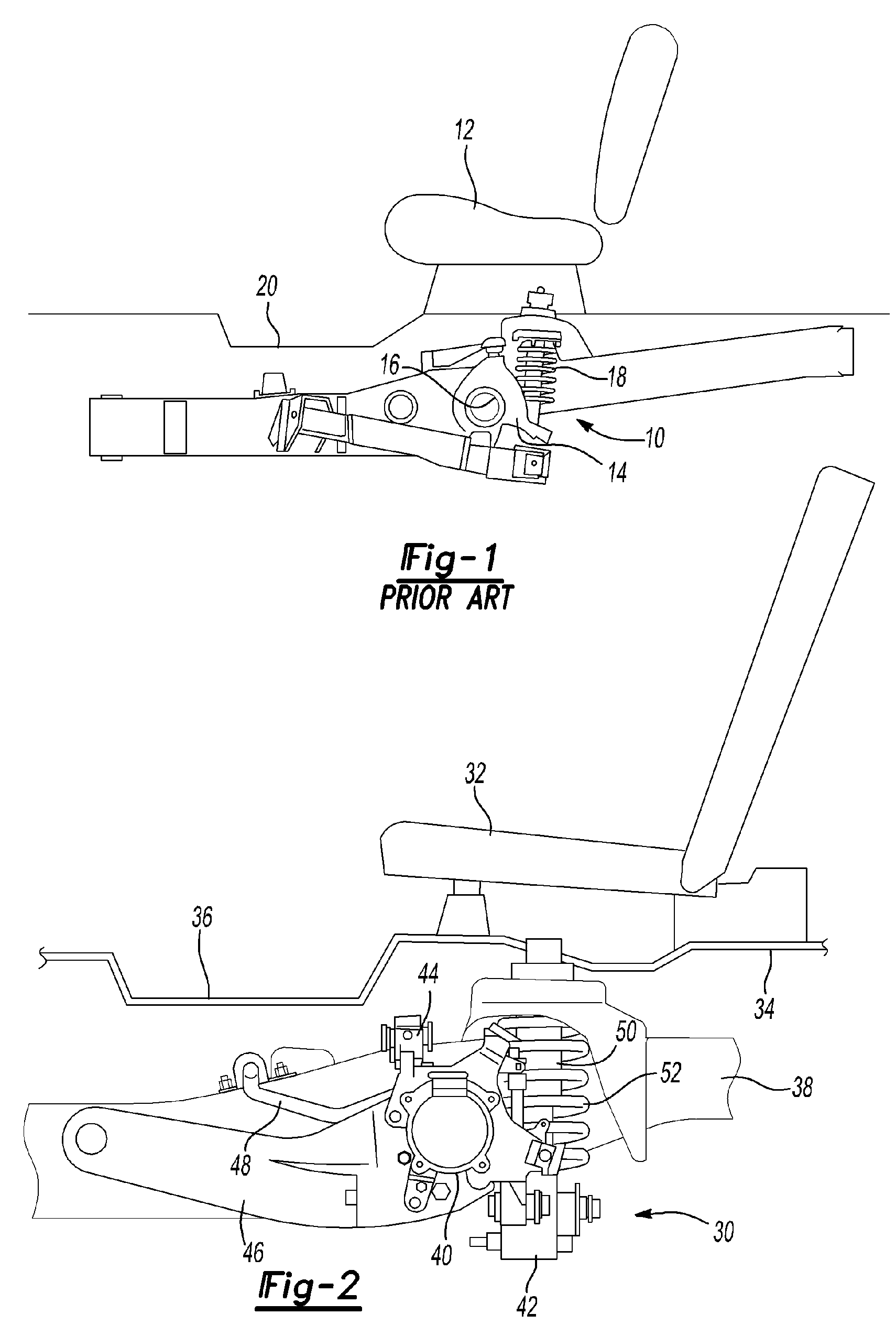
[0028]Referring to FIG. 1, a diagrammatic representation of a prior art independent rear suspension system 10, similar to that disclosed in U.S. Pat. No. 6,109,631, is provided. The suspension system 10 is located below the third row seat 12 of a sport utility vehicle. A wheel support knuckle 14 defines an axle bore 16 through which a rear axle of the vehicle extends. The axle is supported by a combined shock and spring assembly 18 and is disposed rearward of the axle bore 16 and below the rear portion of the third row seat 12 that is secured to the vehicle floor pan 20. The tow link (not shown) is located rearward of the axle center.

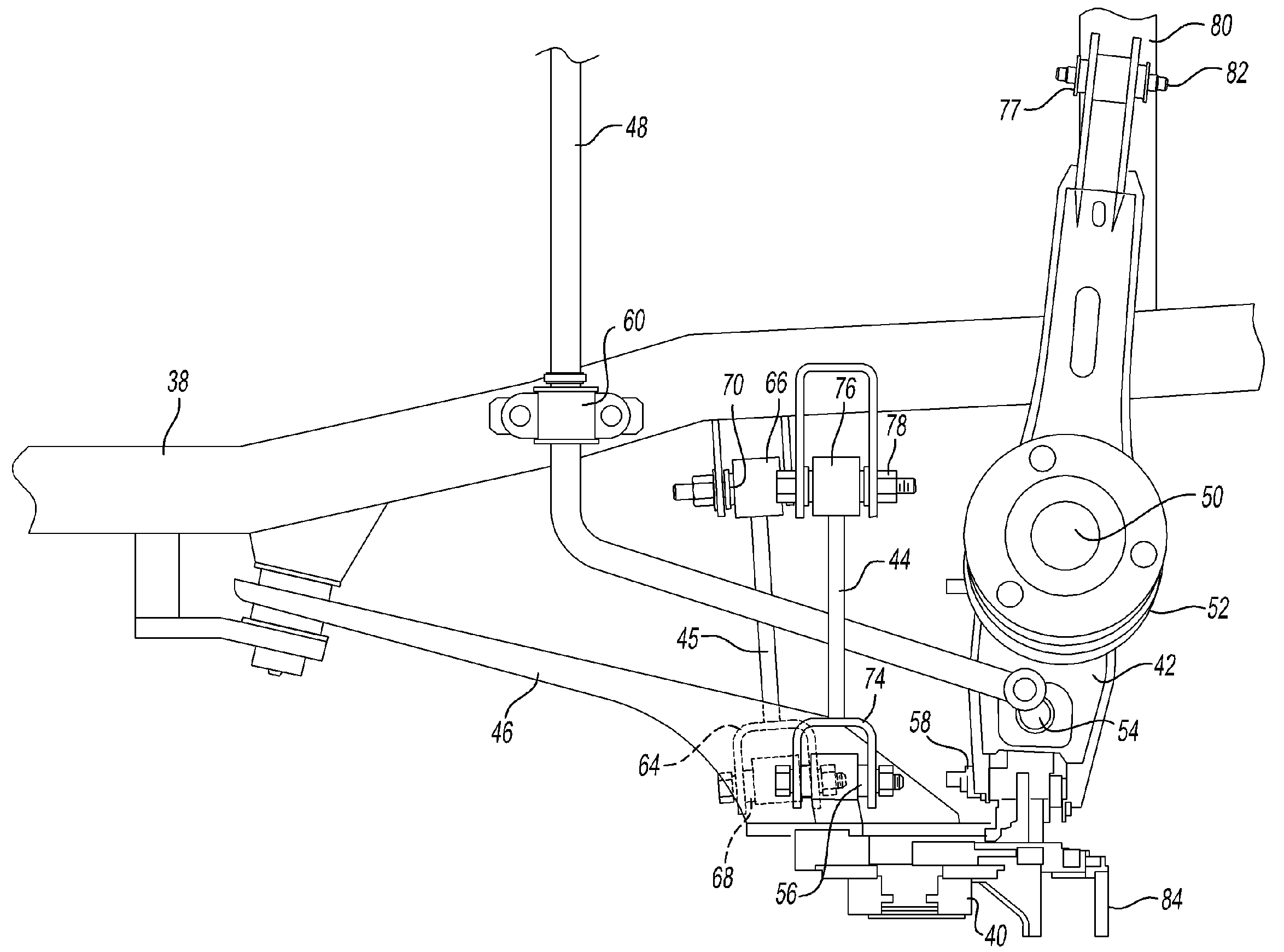
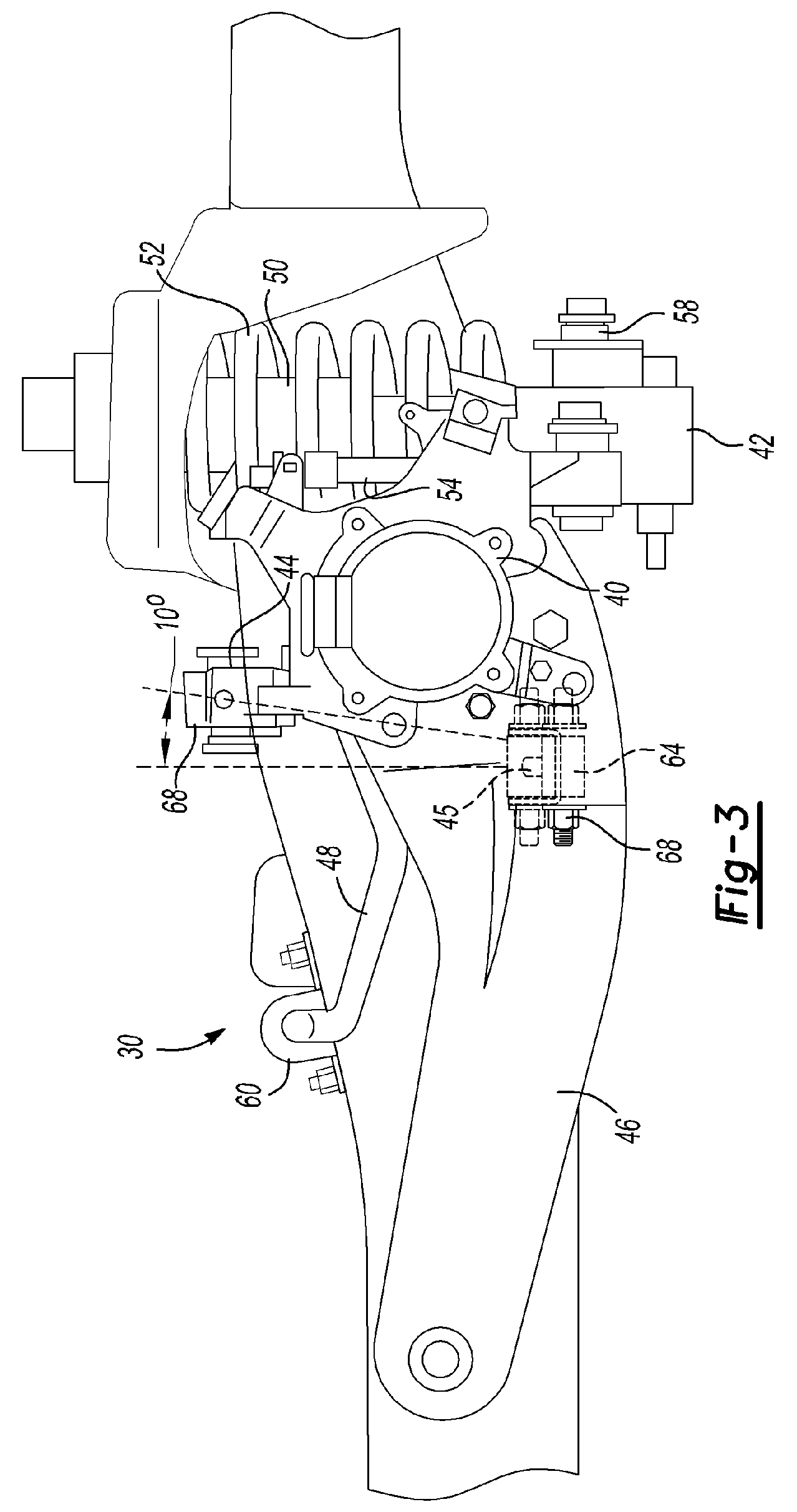
[0029]Referring to FIG. 2, an independent rear suspension system 30 made according to one embodiment of the present invention is shown. The suspension system 30 is located below the third row seat 32 of a sport utility vehicle. A floor pan 34 of the vehicle defines a foot well 36 forward of the third row seat 32. The vehicle is supported by the suspens...


PUM


Abstract

An independent rear suspension system is provided that has a trailing arm connected between a frame rail and a wheel support knuckle. A lower control arm is connected between a frame cross member and the knuckle. The suspension system also includes an upper link that extends between the frame rail and the knuckle. The toe link and upper link are generally vertically aligned. A stabilizer bar extends between the toe link and upper link and is connected to the lower control arm outboard of the shock and spring to reduce space requirements for the suspension system forward of the wheel support knuckle. The lower control arm is elongated and attached to the frame cross member inboard of the frame rails to improve the ratio of wheel travel to shock travel.

Description

BACKGROUND OF THE INVENTION[0001]1. Field of the Invention[0002]The present invention relates to an independent rear suspension for a vehicle, such as a sport utility vehicle having a third row of seats.[0003]2. Background Art[0004]Independent rear wheel suspension systems generally are comprised of shock absorbers, springs and links between the frame of the vehicle and a wheel support knuckle. Upper and lower links, or control arms, generally form an articulated link that allows the vehicle to move vertically relative to the wheel. The shock absorbers and springs are generally provided to absorb impacts to the wheel and provide a smooth ride. Adjustable camber links and toe links are provided to permit adjustment of the wheel position. A stabilizer bar is generally provided to equalize forces laterally by coupling transversely aligned independent suspensions.[0005]Suspension systems are designed to provide the desired ride and handling characteristics for a vehicle. Sports cars are...

Claims


Application Information

Patent Timeline
Patent Type & Authority Patents(United States)
IPC IPC(8): B60G3/00
CPCB60G3/18B60G7/008B60G2200/182B60G2200/184B60G2202/135B60G2204/1222B60G2204/1224B60G2204/148B60G2206/50
Inventor ALLEN, STEVEADAMO, TONYJARGOWSKY, PETERALLARD, CHRISMILLER, BRIAN
Owner FORD GLOBAL TECH LLC
Why Eureka
Try Eureka