
Compact fault tolerant variable cross-drive electromechanical transmission

a cross-drive, electromechanical technology, applied in the direction of electric propulsion mounting, transportation and packaging, gearing, etc., can solve the problems of difficult alignment of bevel gear meshes, low consideration of fault tolerance in the transmission architecture, and high cost of manufacture and maintenan

Active Publication Date: 2008-02-05
BAE SYSTEMS CONTROLS INC
View PDF7 Cites 44 Cited by
  • Summary
  • Abstract
  • Description
  • Claims
  • Application Information

AI Technical Summary

Benefits of technology

The present invention provides a transmission drive system for a differential speed steered vehicle, such as a tank or armored personnel carrier, with two AC induction traction motors and two AC induction steering motors. The system includes a steering gear assembly, two planetary gear sets, two offset gears, and two clutch mechanisms. The system also includes two AC induction pump motors and two semi-independent electronics modules for power and control of the motors and steering motors. The system further includes two mechanical braking subassemblies and is sealed against the ingress of foreign gas, liquid or particulate. The system delivers output speed and torque to two output couplings, tolerant of misalignment.

Problems solved by technology

Further, little if any consideration is given to fault tolerance in the transmission architecture.
Bevel gear meshes are difficult to align, expensive to manufacture and maintain, and prone to premature wear.
The permanent magnets of brushless DC motors are prone to demagnetization at elevated temperatures.
Further, permanent magnet DC brushless motors have significant speed limitations arising from the back EMF inherent with fixed magnetic flux.
The only solution is to provide additional windings to oppose the fixed magnetic flux of the permanent magnets at high speed, which adds weight, complexity and opportunity for failure.

Method used


Image

  • Compact fault tolerant variable cross-drive electromechanical transmission
  • Compact fault tolerant variable cross-drive electromechanical transmission
  • Compact fault tolerant variable cross-drive electromechanical transmission

Examples


Embodiment Construction

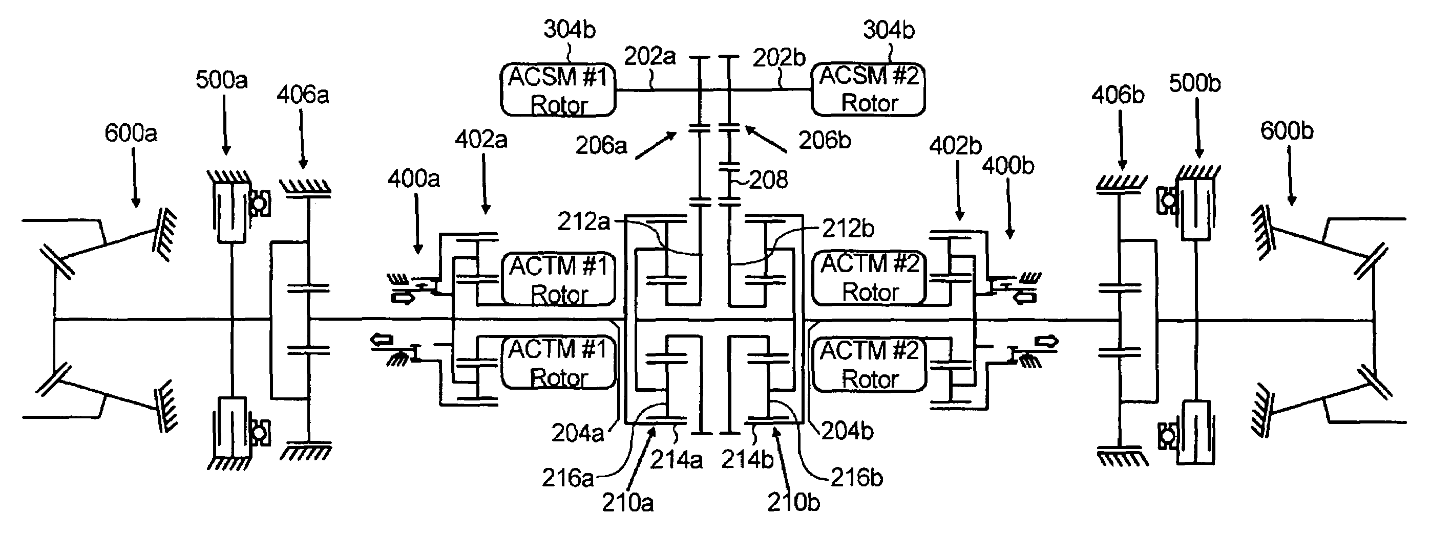
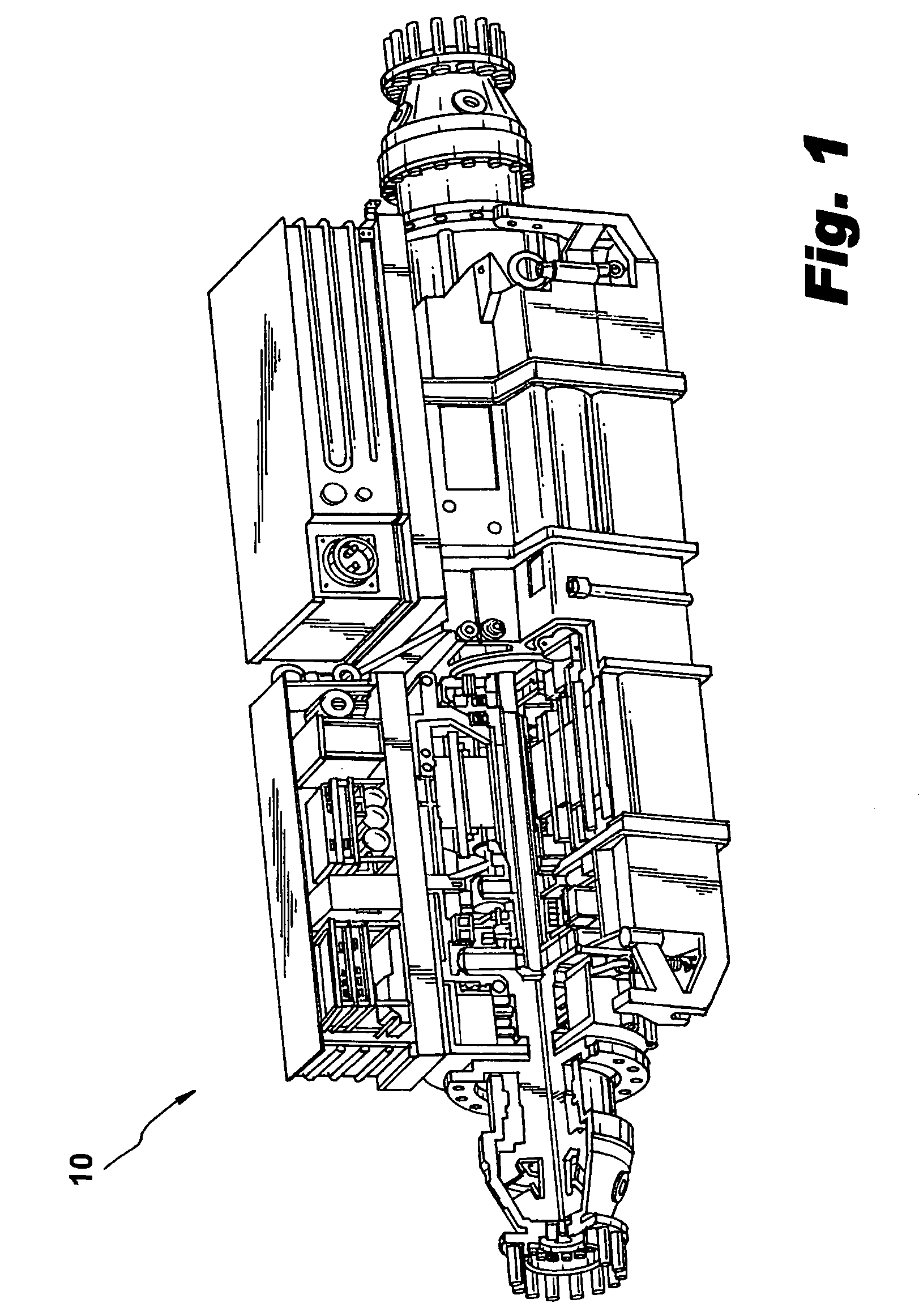
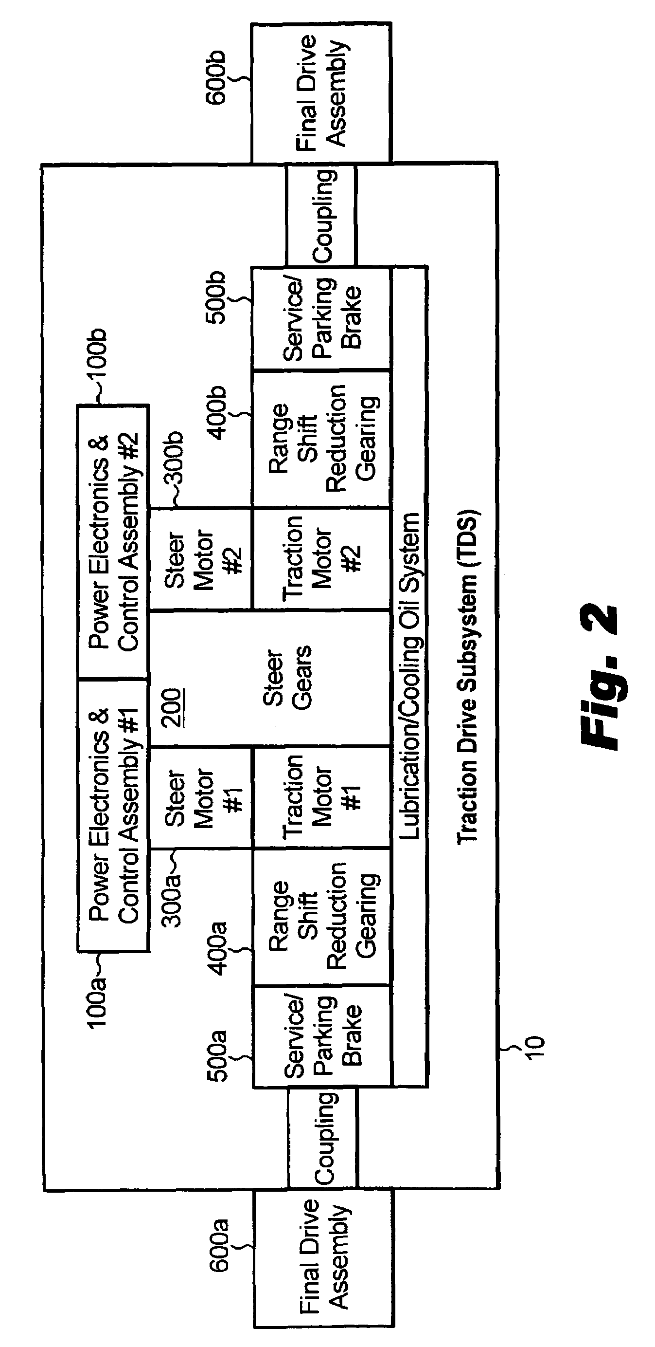
[0027]Referring now to FIG. 1, illustrated in partial cutaway view is a transmission drive system (TDS), generally 10, according to an exemplary embodiment of the present invention. A functional block diagram of the TDS 10 is illustrated in FIG. 2, with the subassembly components in their relative spatial positions to one another. In a preferred embodiment, the TDS 10 is comprised of nine subassemblies, five of which are functionally distinct. The TDS 10 includes two independent Power Electronics Control (PEC) assemblies, 100a, 100b; a single Steer Gear Assembly (SGA) 200; two Motor Housing Assemblies (MHA) 300a, 300b, are positioned on either side of the SGA 200; two Range Shift & Reduction Gear (RSRG) assemblies 400a, 400b are positioned outboard of the MHAs 300a, 300b; and two Service / Parking Brake (SPB) assemblies 500a, 500b are located outboard of the RSRGs 400b, 400b. Hereinafter, where two identical subassemblies are described, for example PECs 100a, 100b, they may be collect...


PUM


Abstract

A transmission drive system (TDS) has two AC induction traction motors, each operatively coupled to two semi-independent coaxial traction shafts, and two AC induction steer motors coaxially mounted on a common steer axis parallel to the coaxial traction shafts. A steering gear assembly, preferably between the traction and steering motors, has a common steer input shaft operatively connected to the two AC induction steering motors. Two planetary gear sets have the two traction shafts being operatively connected with one of a two planet gear carriers, or two ring gears, respectively. The other of the planet gear carriers or the ring gears are operatively connected with each other. Two offset gears mounted to the steer input shaft and meshing with two sun gears, respectively, including a reversing idler gear interposed between one of the two offset gears and one of the two sun gears.

Description

BACKGROUND OF THE INVENTION[0001]1. Field of Invention[0002]The invention relates to the field of transportation, and more specifically to a cross-drive transmission particularly applicable for use in differential speed-steered vehicles, particularly track-laying vehicles.[0003]2. Description of Related Art[0004]The use of mechanical cross-drive transmissions employing mechanical, electrical or hydraulic steering devices in tracked and other differential speed-steered vehicles has been known since approximately World War I and World War II. There is currently a growing interest in the art in using cross-drive technology in combination with exclusively electric motors to provide both drive power and steer power, the electric motors being powered by on-board engine-generator set and / or on-board stored electrical energy. Indeed certain arrangements of electro-mechanical cross-drives have been attempted in the art, with certain deficiencies.[0005]Among these deficiencies, the cross-driv...

Claims


Application Information

Patent Timeline
Patent Type & Authority Patents(United States)
IPC IPC(8): B62D11/06
CPCB60K7/0007B62D11/14B62D11/16B60K17/046B60K2007/0038Y10T477/10B60K2007/0092
Inventor LYONS, ARTHUR P.MANCINI, BART WINTER
Owner BAE SYSTEMS CONTROLS INC
Learn More