Process for laying fiber tape

a fiber tape and fiber board technology, applied in the direction of transportation and packaging, packaging, paper/cardboard articles, etc., can solve the problems of affecting the safety of parts, requiring many passes of the tape head over the part, and wasting time, so as to achieve the effect of reliable removal of scrap tape sections

Active Publication Date: 2008-02-05
WELLS FARGO BANK NAT ASSOC +1
View PDF10 Cites 28 Cited by
  • Summary
  • Abstract
  • Description
  • Claims
  • Application Information

AI Technical Summary

Benefits of technology

[0008]It is accordingly an object of the invention to provide a method for reliably removing scrap sections of tape between courses of tape so that the scrap sections of tape may be successfully deposited in a scrap area.

Problems solved by technology

As a result, the laying up of an aircraft component such as a control surface or a wing requires many passes of the tape head over the part, and several hours of time.
Non-full width courses present special problems.
Either event causes a manufacturing defect in the part which may render the part unsafe.

Method used


Image

  • Process for laying fiber tape
  • Process for laying fiber tape
  • Process for laying fiber tape

Examples


Embodiment Construction

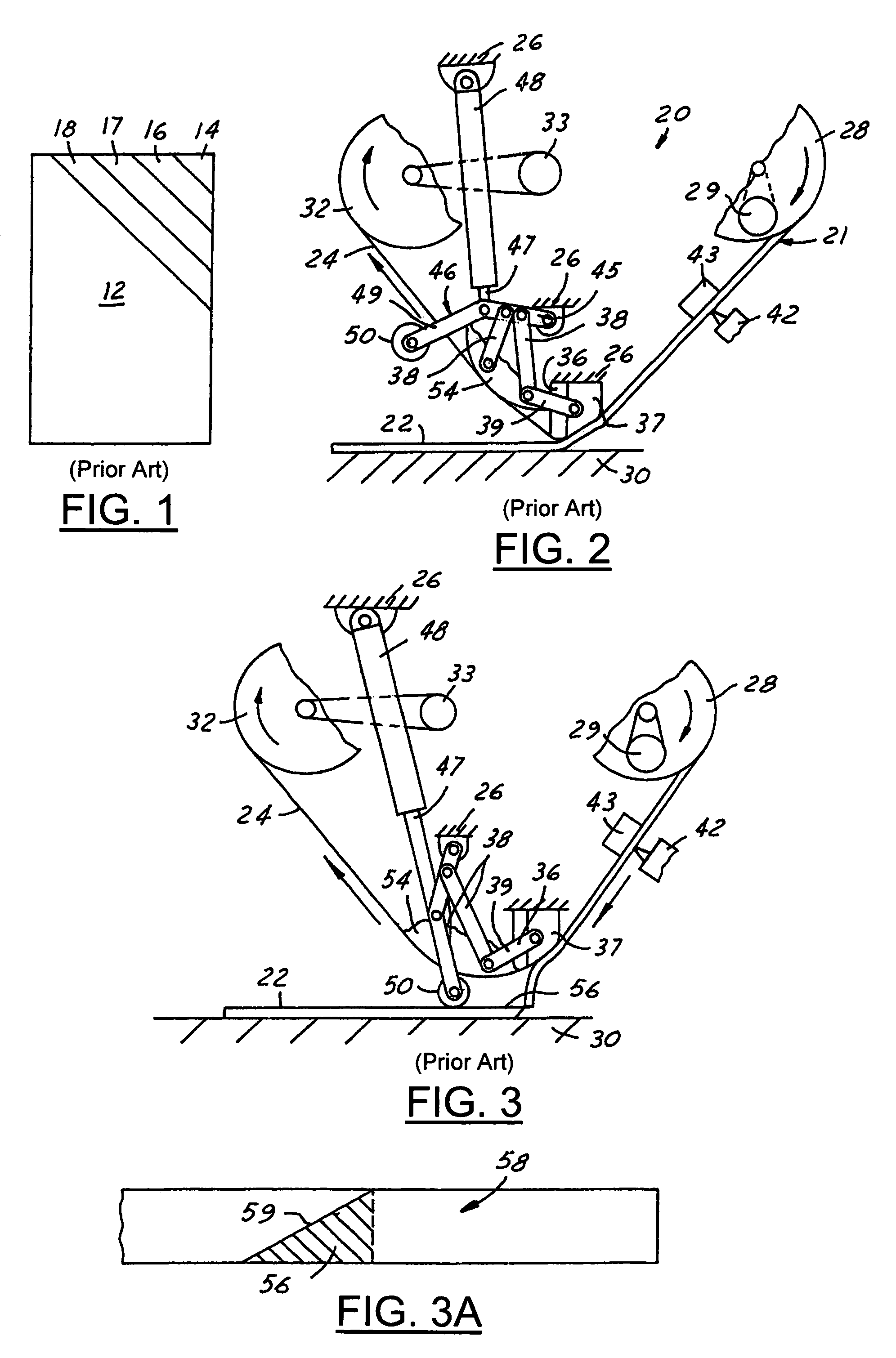
[0025]Turning now to the drawing figures, FIG. 1 shows a typical pattern used to lay fiber tape on a part 12. The first course of tape 14 is laid in the corner of the part and has the shape of a triangle. The second course of tape 16 is laid adjacent to the first course 14, and has the shape of a trapezoid; the third and fourth courses of tape 17 and 18 are laid adjacent to the immediately preceding course, and have the shape of a trapezoid. Additional courses of tape (not shown) are laid on the part until the entire surface of the part is covered. A second layer of tape is then applied over the first layer of tape using the same process. The second layer of tape is often applied at an angle of 30 degrees or more to the first layer of tape in order to increase the strength of the resulting part. Additional layers of tape are applied to the previous layers until the laminated structure reaches the desired thickness. Often hundreds of layers may be required to form the desired fiber c...


PUM

PropertyMeasurementUnit
widthsaaaaaaaaaa
widthsaaaaaaaaaa
widthsaaaaaaaaaa

Abstract

The process for laying a non-full width course of fiber composite tape in a part is designed to ensure that all of the scrap portion of the tape surrounding the non-full width course is deposited in the scrap area and not in the part. An extra cut is made in tape downstream of the non-full width course, between the non-full width course and next course. After the tape head attempts to lay the scrap in the scrap area in the forward direction, the tape head makes a pass in the scrap area with the tape feed and the tape head moving in the reverse direction, and the scrap is laid beginning from the portion of the tape having the extra cut, and progressing to the non-full width course. The method may be used to remove scrap from around non-full width courses having any shape.

Description

FIELD OF THE INVENTION[0001]The invention relates to processes for ensuring the removal of scrap portions of fiber tape between courses of tape that are to be laid in a part by a computer controlled tape laying machine.BACKGROUND OF THE INVENTION[0002]The use of fiber composite tape laying machines for the manufacture of fiber composite parts is well known in the art. Such machines comprise a tape laying head mounted on the end of a cantilever arm that is supported for complex motion in order to apply fiber tape to a form or tool in order to create a part. The head normally travels in one direction along the tool and applies the fiber tape to the tool as it moves across the surface of the tool. The fiber tape comprises a resin matrix in which are embedded bundles of carbon fiber. The fiber tape is applied to a carrier layer of backing paper that is coated with a release agent. A feed reel on the head provides a supply of tape, and a take-up reel is provided to take up the backing pa...

Claims


Application Information

Patent Timeline
Patent Type & Authority Patents(United States)
IPC IPC(8): B32B37/00
CPCB29C70/388B29C70/545Y10T156/1064Y10T156/1085B29C2793/0027
Inventor RUST, RALPH JOHNGRIMSHAW, MICHAEL NORTHHECHT, JAMES RICHARD
Owner WELLS FARGO BANK NAT ASSOC
Why Eureka
Try Eureka