Impact energy absorbing structure

a technology of energy absorption and impact, applied in the direction of shock absorbers, elastic dampers, pedestrian/occupant safety arrangements, etc., to achieve the effect of reducing the impact of passengers, efficient absorption of kinetic energy during collisions, and improving the impact energy absorption pattern

Inactive Publication Date: 2008-02-05
SUMITOMO CHEM CO LTD
View PDF2 Cites 0 Cited by
  • Summary
  • Abstract
  • Description
  • Claims
  • Application Information

AI Technical Summary

Benefits of technology

[0012]This makes it possible to provide an impact energy absorbing structure that is capable of efficiently absorbing kinetic energy during collision to alleviate the impact to passenger heads in particular while preserving space inside the vehicle, and that also has performance with a better impact energy absorbing pattern than the rectangular wave form which has conventionally been considered ideal. Although any material such as a resin, metal, or ceramic can be used for the material of the impact energy absorbing structure, resins are preferred because of advantages such as good formability, light weight, and ease of mass production.
[0013]Also the impact energy absorbing structure of this invention preferably comprises a substrate; an impact receiving member disposed parallel to the substrate; and a plurality of impact energy absorbing members that are disposed between the substrate and the impact receiving member, that deform while exerting repulsion on the colliding object, and that break when the critical deformation level is reached, wherein the critical deformation levels of each of the impact energy absorbing members are established stepwise within said permissible deformation range, and the repulsion of each of the impact energy absorbing members is set so as to meet the relationship between the dimensionless displacement D and dimensionless energy E defined in Formula (1). By differentiating properties of dimensionless energy (absorbed kinetic energy) relative to the dimensionless displacement of the aforementioned impact energy absorbing structure, the properties of dimensionless repulsion (load) relative to the dimensionless displacement of the impact energy absorbing structure can be found. The aforementioned structure makes it possible to easily produce an optimal model (model in which HIC(d) is minimized, with low permissible deformation) represented by such properties. That is, because dimensionless displacement is used as a parameter instead of time, the discrete values of such dimensionless displacement can correspond to the critical deformation of the impact energy absorbing members. Because the dimensionless repulsion is treated as a value, it can correspond to the synthetic repulsion of impact energy absorbing members that are not broken up, thereby making it possible to provide an impact energy absorbing structure with which an optimal model is readily realized.

Problems solved by technology

As a result, a major issue in the design of actual products has been how to make the deformation behavior (time-acceleration behavior of colliding object) more closely resemble a rectangular wave.

Method used


Image

  • Impact energy absorbing structure
  • Impact energy absorbing structure
  • Impact energy absorbing structure

Examples


examples

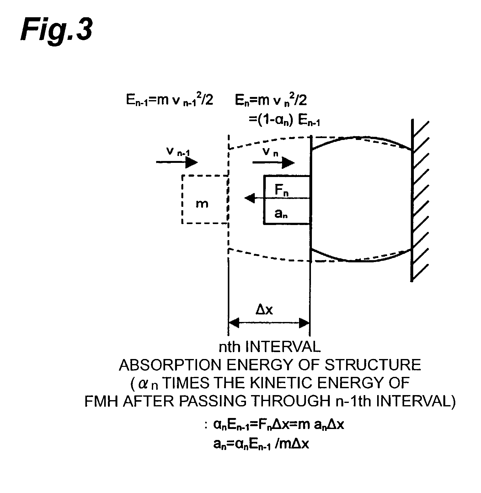
[0050]The patterns of αn (0≦αn≦1:n=1, 2, . . . , M) with minimum HIC(d) were actually determined for various permissible deformation levels S by the method described above. M=10 was established using “iSIGHT” (ver 5.1) by Engineous Software, Inc. as the optimization software and simulated annealing as the optimization method. The permissible deformation S serving as a condition was suitably spread out between 10 and 60 mm.

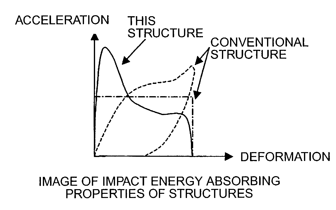
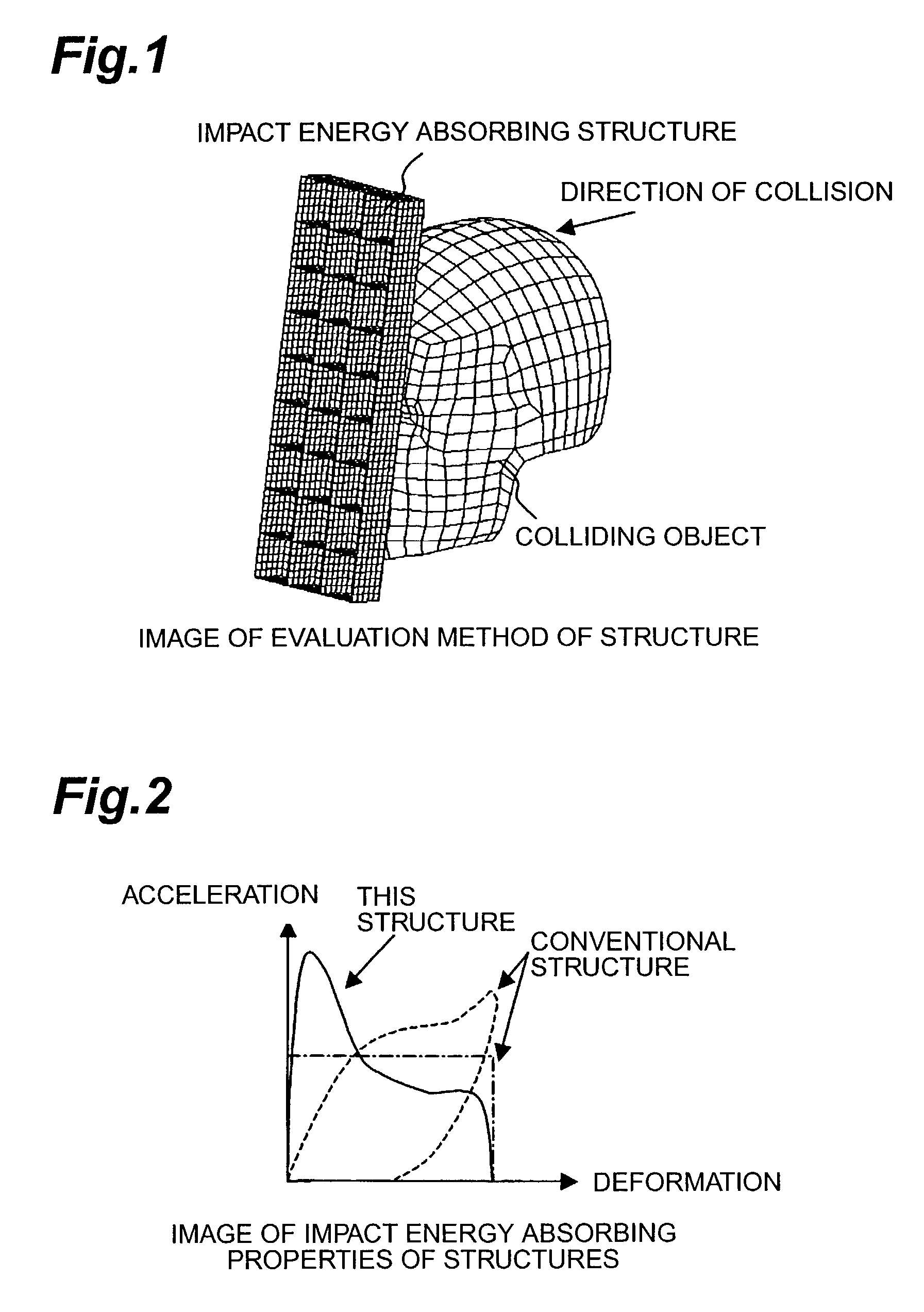
[0051]FIGS. 5 through 10 show the deformation behavior at the various permissible deformation levels S calculated on the basis of the patterns of αn (0≦αn≦1:n=1, 2, . . . , M) giving minimum values. In these figures, the horizontal axis is the dimensionless deformation, which is obtained by dividing the deformation by the permissible deformation S, and the vertical axis is the dimensionless acceleration, which is obtained by dividing the acceleration of each deformation interval by the maximum acceleration. Because the product of the acceleration and deformation is...


PUM

PropertyMeasurementUnit
velocityaaaaaaaaaa
massaaaaaaaaaa
impact energyaaaaaaaaaa

Abstract

An object of the invention is to provide an impact energy absorbing structure in the form of resin moldings such as interior components of automobiles and other impact energy absorbing structures, with better impact properties, particularly the performance in absorbing impact energy to passenger heads. The invention relates to an impact energy absorbing structure for absorbing the kinetic energy of a colliding object by means of its own deformation, wherein when a certain colliding object collides with the impact energy absorbing structure at a certain velocity, the relationship between dimensionless displacement D, where the deformation of the impact energy absorbing structure is normalized by the permissible deformation, and the dimensionless energy E, where the kinetic energy absorbed by the impact energy absorbing structure is normalized by the kinetic energy of the colliding object prior to collision, meets E>D.

Description

BACKGROUND OF THE INVENTION[0001]1. Field of the Invention[0002]The present invention relates to an impact energy absorbing structure which is used to absorb impact energy on the heads of passengers during collisions in vehicles, for example.[0003]2. Related Background Art[0004]In order to ensure higher levels of passenger protection in the interior of vehicles such as automobiles, the recent trend has been toward the establishment of increasingly stringent standards regarding passenger safety measures and the like. In the United States, in particular, the Federal Motor Vehicle Safety Standards have been strengthened (FMVSS 201U), resulting in more stringent regulations regarding measures for protecting passenger heads. In FMVSS 201U, dummy heads (mass 4.54 kg) referred to as free motion headforms (FMH) are used as the colliding object, which is caused to collide on an interior part (impact energy absorbing structure) at 24 km / h, and the total acceleration a (t) at the FMH center of...

Claims


Application Information

Patent Timeline
Patent Type & Authority Patents(United States)
IPC IPC(8): B32B9/00F16F7/12B60R21/04B60R13/02B60R21/00B60R21/01B60R21/015F16F7/00
CPCB60R21/0156F16F7/12B60R2021/0048Y10T428/31504
Inventor HIROTA, TOMOOTOGAWA, YOSHIAKI
Owner SUMITOMO CHEM CO LTD
Why Eureka
Try Eureka