
Digital readout system

a digital readout and signal technology, applied in the field of signal detection, can solve the problems of a second type of simultaneous multiple, a critical affecting the final image produced, and the unresponsive of the detector, so as to increase the utility of the system, fast readout time, and effectively queue the effect of requesting signals

Active Publication Date: 2008-02-05
GE MEDICAL SYST ISRAEL
View PDF5 Cites 8 Cited by
  • Summary
  • Abstract
  • Description
  • Claims
  • Application Information

AI Technical Summary

Benefits of technology

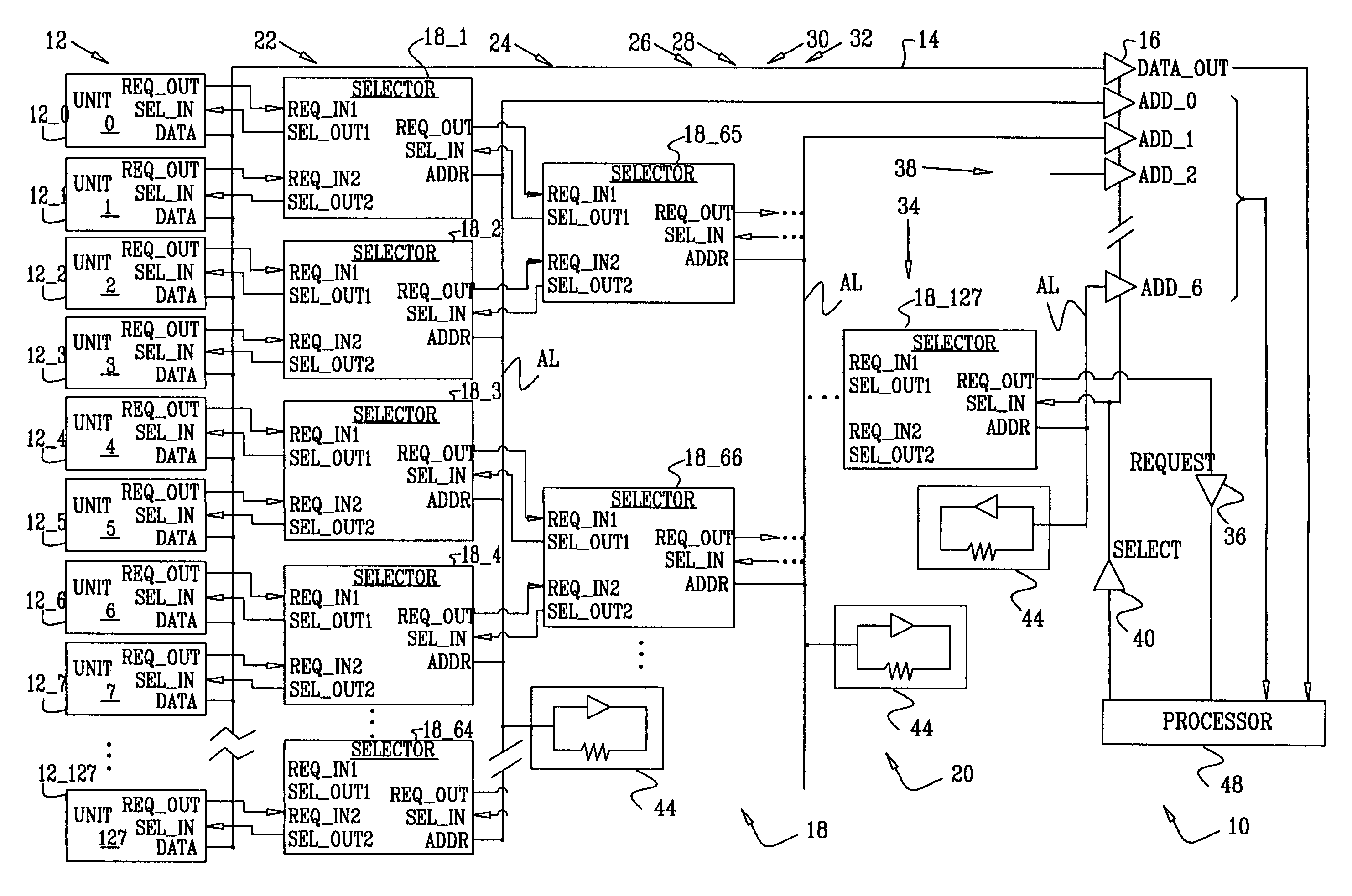
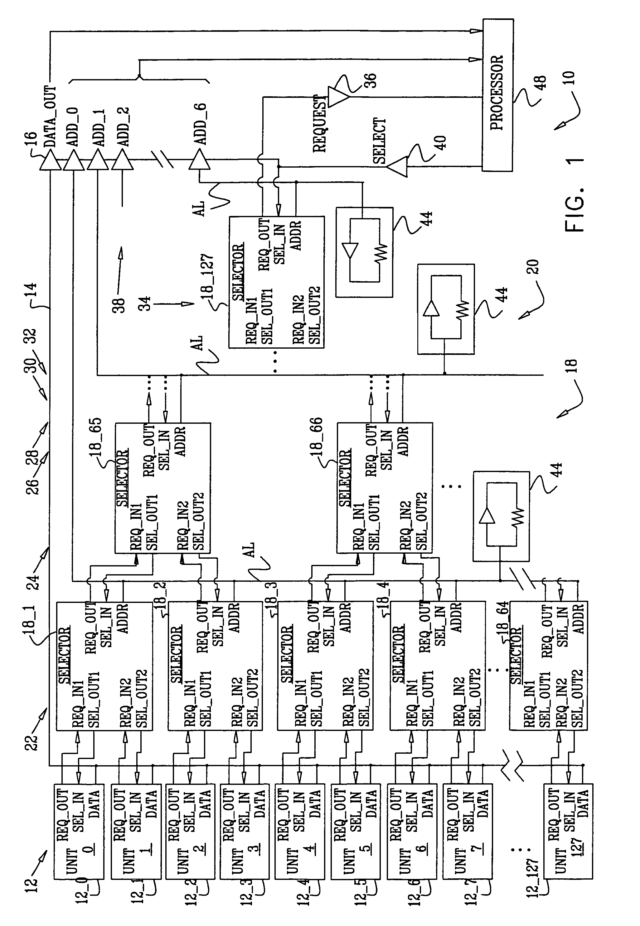
[0012]The array of units is coupled to a set of selectors, all substantially similar, which are connected together in the form of a tree. The tree is arranged in rows, each row having fewer selectors than a preceding row. Typically, each row has half the number of selectors of the preceding row. A final row of the tree consists of one final selector. A request signal from a unit having the indication is routed forward through the tree by the selectors to the final selector, and from there to a processor. The processor generates a select signal that is routed back, via the same selectors, to the unit originating the request signal. In addition, on receipt of the request signal, the processor activates the readout amplifier, so that the indication on the originating unit is read by the processor. Coupling the units to selectors which are arranged in the form of a tree, and which are able to route signals through the tree forward and back along the same path, forms an event-driven unit readout system having an extremely fast readout time.
[0013]In addition to being configured to route the select signal along the same path as the request signal, the selectors are also configured to retain other request signals, and to forward these signals to the final selector as, and when following selectors are free, i.e., are not transferring another request signal or a select signal. Combined with the event-driven system described above, the added ability of the selectors to effectively queue request signals by acting as memory elements substantially increases the utility of the system.
[0037]Typically, the second plurality of selectors are coupled to receive and store two or more request-to-read signals from respective two or more detector units having respective two or more indications stored therein, and the method includes receiving the two or more request-to-read signals and in response transmitting respective two or more select signals via the second plurality of selectors to the respective two or more detector units, thereby causing reading of the respective two or more indications.

Problems solved by technology

Consequently, in the time period between charge generation and detector's readout unit reset, any photons incident on the detector are unread, so that in this time period the detector is unresponsive.
Arrival of a photon at the detector during the unresponsive time period of the detector defines a first type of “simultaneous multiple-event.” For systems having even relatively low photon rates, the loss of information caused by this type of simultaneous multiple-event, leading to unread events, may critically affect the final image produced.
This process may relax, at least somewhat, the requirement for a fast detector readout, but may cause problems at the occurrence of a second type of simultaneous multiple-events.
Adjusting the detector to only respond to a specific range of levels may thus mean that photons causing the second type of multiple event go undetected.

Method used


Image

  • Digital readout system
  • Digital readout system
  • Digital readout system

Examples


Embodiment Construction

[0043]Reference is now made to FIG. 1, which is a schematic block diagram of a digital readout system 10 for detecting radiation, according to an embodiment of the present invention. System 10 comprises a multiplicity of detector units 12, herein also referred to as units and assumed by way of example to comprise 128 units. However, it will be appreciated that the number of units in system 10 may be any convenient whole number equal to or greater than two. In the specification the units are referred to generically as units 12, and specifically as unit n or unit 12—n, where n is an integer from 0 to 127.

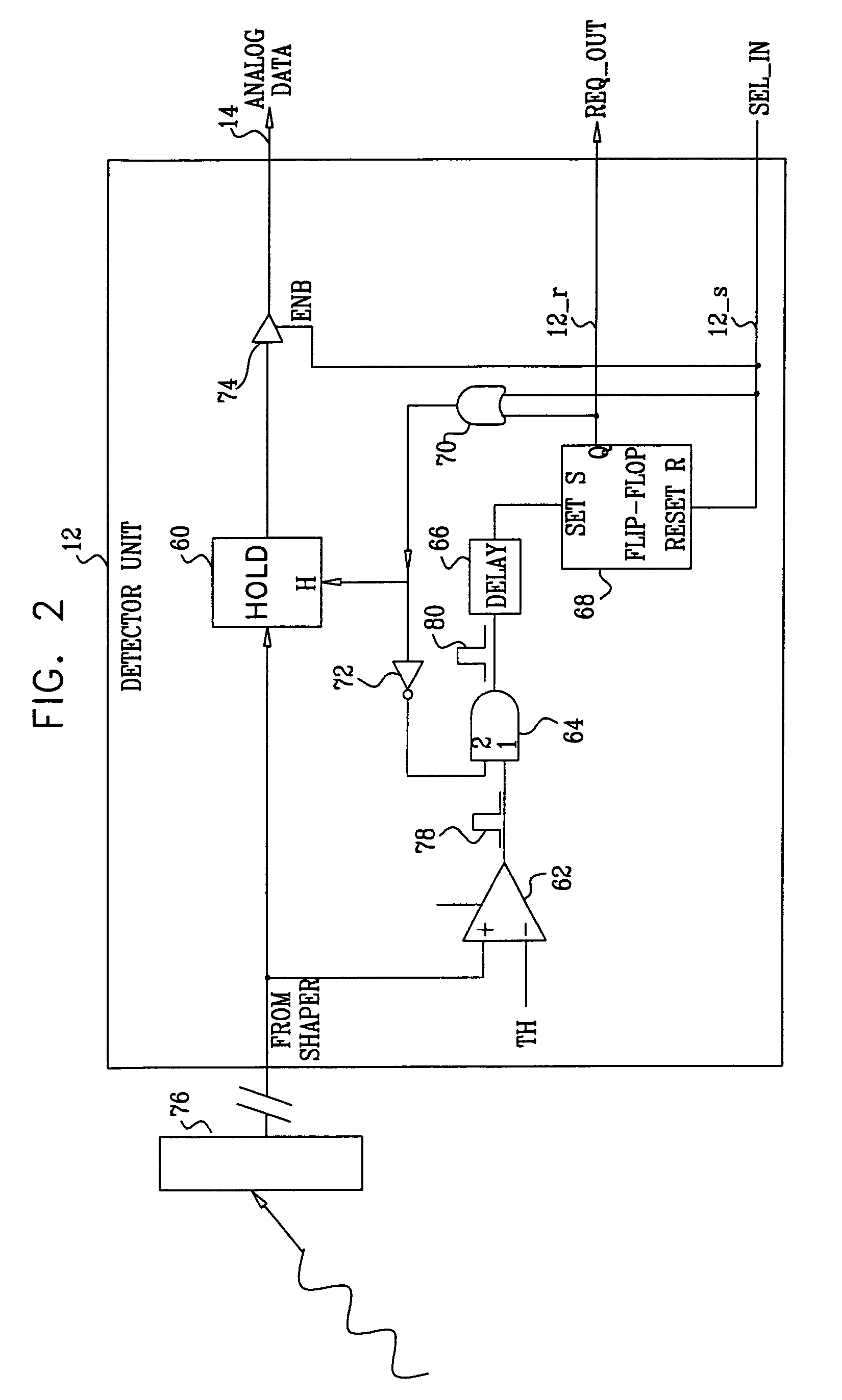
[0044]As explained in more detail below, each unit 12 detects single photons, outputting a detected signal on a data channel 14, typically a bus line. The detected signal is transferred to a processor 48 via a readout amplifier 16. Processor 48 may comprise a field programmable gate array (FPGA), and / or any other convenient processor such as an industry-standard computing unit. Units ...


PUM


Abstract

A readout system, including a data channel for conveying data, and detector units. Each detector unit includes an input which receives a pulse having a magnitude, a storage buffer which stores an indication of the magnitude, and output circuitry which outputs a request-to-read signal in response to the storage unit receiving the pulse. The units output the indications to the data channel upon receiving a select signal in response to the request-to-read signal. The system includes a processor, which receives the request-to-read signal, and in response transmits the select signal and reads the indication from the data channel. The system also includes selectors, coupled as a tree of hierarchical rows having decreasing numbers of selectors, which convey the request-to-read signals from the detector units to the processor. The selectors also convey the select signals from the processor to the detector units, thereby causing the processor to read the indications.

Description

FIELD OF THE INVENTION[0001]The present invention relates generally to signal detection, and specifically to a system for reading detectors of the signals.BACKGROUND OF THE INVENTION[0002]Arrays of detectors are used in imaging systems operating with high-energy photons, such as X-ray or y-ray cameras. Depending on its mode of operation, each detector of the array converts a detected photon, directly or indirectly, to a measurable electrical parameter, herein assumed to be a charge, which is a function of the energy of the detected photon. Typically, both the number of detected photons within a specific time period, and the energies of the detected photons, may be used to construct an image of the object generating the photons.[0003]Once a detector has detected a photon, the detector is effectively disabled until the charge it generates has been read from the detector and the detector readout unit has been reset. Consequently, in the time period between charge generation and detecto...

Claims


Application Information

Patent Timeline
Patent Type & Authority Patents(United States)
IPC IPC(8): G01J1/44H01J40/14H03F3/08
CPCG01T1/17H04N25/771H04N25/00H04N25/47H04N25/707
Inventor SHALOM, DANIELSHAHAR, ARIEEL-HANANAY, URISHANI, ALLONTSIGELMAN, ALEX
Owner GE MEDICAL SYST ISRAEL
Learn More