Full-bridge circuit

Active Publication Date: 2008-02-05
DELTA ELECTRONICS INC
View PDF6 Cites 0 Cited by
  • Summary
  • Abstract
  • Description
  • Claims
  • Application Information

AI Technical Summary

Benefits of technology

[0008]Full-bridge circuits are provided. Some embodiments of the full-bridge circuit comprise two control signals utilized for controlling all switches therein to simplify the circuitry. The switches can comprises various types of elements, including low cast elements reducing in circuit cost.

Problems solved by technology

The low voltage elements however have weak anti-noise ability resulting in false operation due to floating voltage in the circuit.
As the number of available low voltage elements is limited, effective cost reduction is difficult.
Moreover, four control signals are required from a MCU to control switches Q1 to Q4 of the full-bridge circuit 12, resulting in complicated circuitry.

Method used


Image

  • Full-bridge circuit
  • Full-bridge circuit
  • Full-bridge circuit

Examples


Embodiment Construction

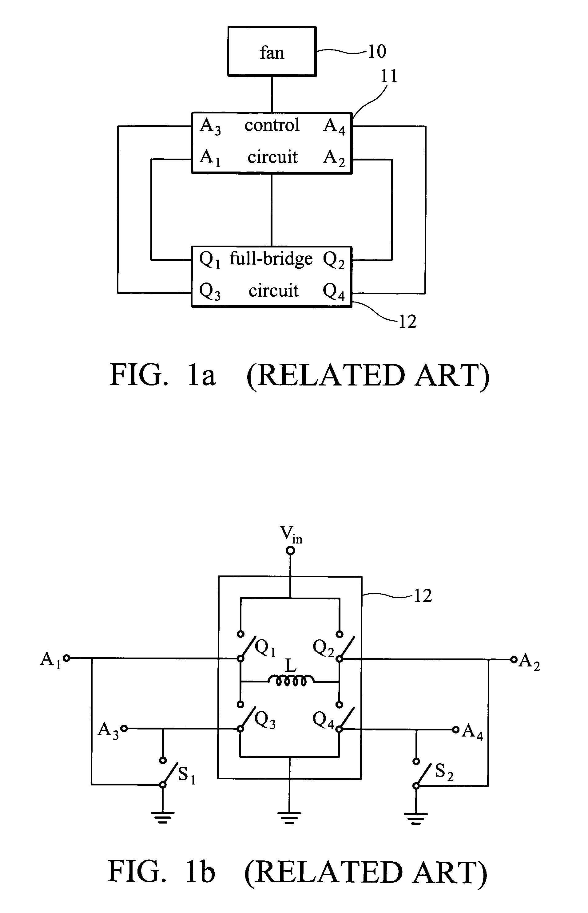
[0019]Full-bridge circuits for heat dissipation system are provided. An embodiment of a full-bridge circuit comprises a fan and a control circuit. The fan dissipates heat for an object. The control circuit outputs control signals to control ON / OFF states of switches within the full-bridge circuit. For example, a micro-processor control unit (MCU) outputs control signals. In other words, blocks of some embodiments of the heat dissipation system are as shown in FIG. 1a.

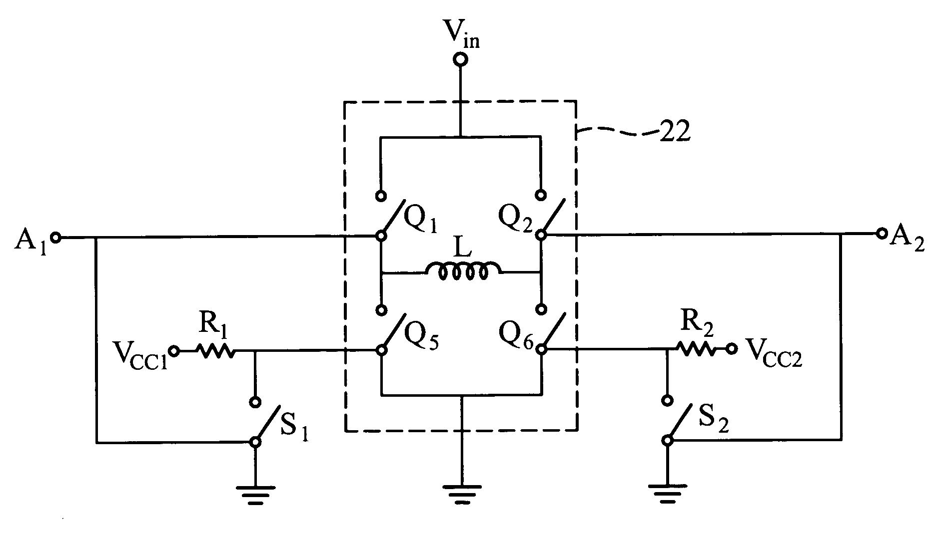
[0020]Referring to FIG. 2, like reference numbers are used to designate like parts throughout the various views and illustrative embodiments. An embodiment of a full-bridge circuit 22 receives two control signals to control ON / OFF states of switches therein. The two control signals are a first control signal from a node A1 and a second control signal from a node A2. The first and second control signals are out of phase.

[0021]As shown in FIG. 2, the full-bridge circuit 22 comprises a first control line, a second control...


PUM


Abstract

A full-bridge circuit for a heat dissipation system. The heat dissipation system further includes a fan and a control circuit. The control circuit outputs a first control signal and a second control signal. The full-bridge circuit includes a first control line having a first switch and a third switch serially coupled, a second control line includes a second switch and a fourth switch serially coupled, and a induction coil having one terminal coupled between the first and third switches and the other terminal coupled between the second and fourth switches. The ON / OFF states of the first and second switches are controlled by the first and second control signals respectively. The ON / OFF states of the third and fourth switches are controlled by two driving voltage sources respectively.

Description

BACKGROUND OF THE INVENTION[0001]1. Field of the Invention[0002]The invention relates to a full-bridge circuit, and in particular to a full-bridge circuit employed in a direct-current fan.[0003]2. Brief Discussion of the Related Art[0004]FIG. 1a is a block diagram of a conventional heat dissipation system. FIG. 1b shows a circuit of the full-bridge circuit in FIG. 1a. As shown in FIG. 1a, the heat dissipation system comprises a fan 10, a control circuit 11, and a full-bridge circuit 12. The full-bridge circuit 12 comprises switches Q1 to Q4 and an induction coil L. When the switches Q1 and Q4 are turned on, the switches Q2 and Q3 are turned off and a current path of an input voltage Vin includes the switch Q1, the induction coil L, and the switch Q4. Conversely, when the switches Q1 and Q4 are turned off, the switches Q2 and Q3 are turned on and a current path of the input voltage Vin includes the switch Q2, an induction coil L, and the switch Q3.[0005]The switches Q1 to Q4 of the f...

Claims


Application Information

Patent Timeline
IPC IPC(8): H02M7/5387H02M3/24H02M7/00H02M1/38H02M3/335
CPCH02M7/53871H02M1/38
Inventor CHIU, MAGELLANCHIU, CHUN-LUNGTSENG, WEI-SHUOTSAI, MING-SHI
Owner DELTA ELECTRONICS INC
Why Eureka
Try Eureka