Method of determining working voltage of inverter

Inactive Publication Date: 2006-03-30
ZIPPY TECH
View PDF1 Cites 4 Cited by
  • Summary
  • Abstract
  • Description
  • Claims
  • Application Information

AI Technical Summary

Benefits of technology

[0006] The primary objective of the present invention is to improve the aforementioned drawbacks, and to provide a method of determining a working voltage of an inverter, wherein a power factor regulator needn't be additionally installed thereto and the circuitry cost thereof is reduced.
[0007] According to one aspect of the present invention, a method of determining a working voltage of an inverter of the present invention utilizes a rectifying method to transform a cycle of an input alternating current into a cycle of a pulse direct current, and transform an alternating current signal into a direct current signal, and then sets a working frequency to divide each one cycle of the pulse direct current into multiple continuous voltage pulses, wherein one cycle of the pulse direct current varies in the lowest voltage—the highest voltage—the lowest voltage manner.

Problems solved by technology

However, the reactive power will incur a line drop and a line loss.
It's the loss both for the power company an

Method used


Image

  • Method of determining working voltage of inverter
  • Method of determining working voltage of inverter
  • Method of determining working voltage of inverter

Examples


Example

[0015] Referring to the attached drawings, the detailed description of the present invention will be stated below.

[0016] For the examiners' definite understanding of the present invention, the embodiments, with respect to inverters utilizing a piezoelectric transformer, will be selected to be described herein, and as the embodiments, with respect to inverters utilizing a winding transformer, operate similarly, those will not be repeated herein. Figures of voltage or current waveforms will be utilized to aid the description herein.

[0017] According to one embodiment of the present invention, the operational steps of the present invention include:

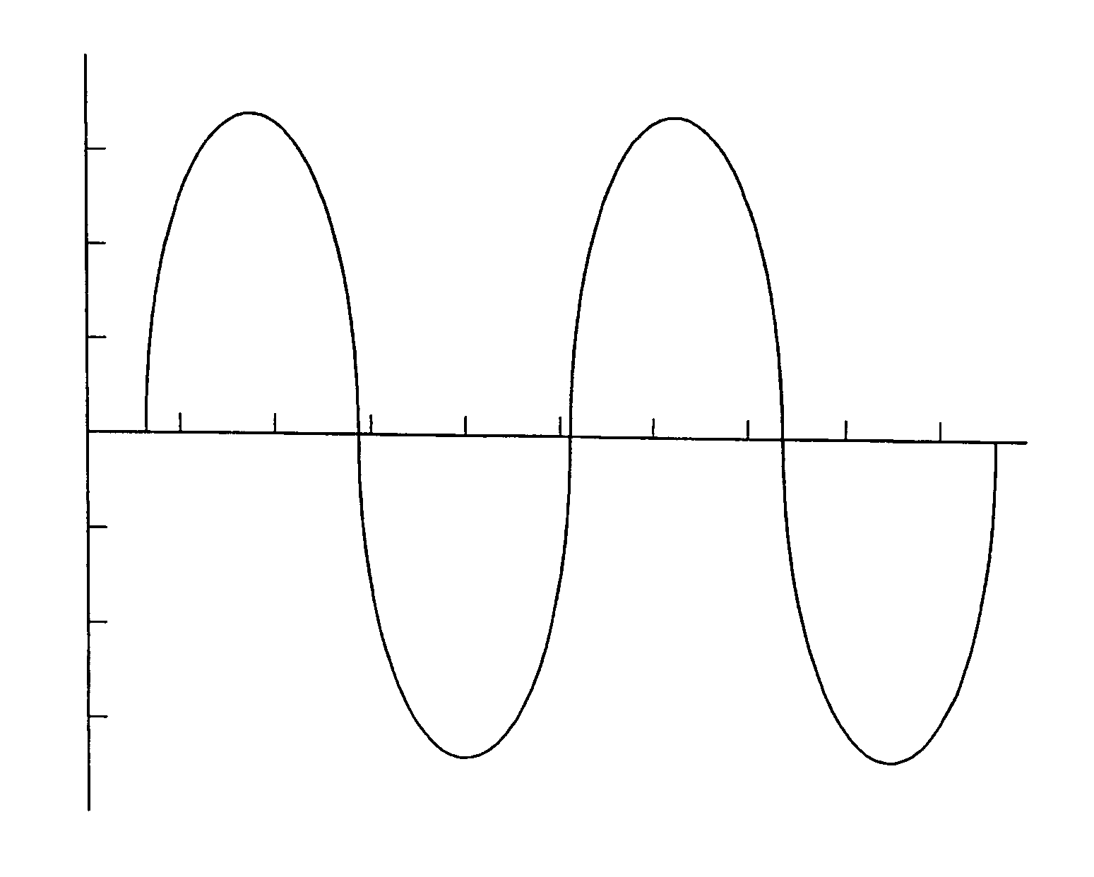
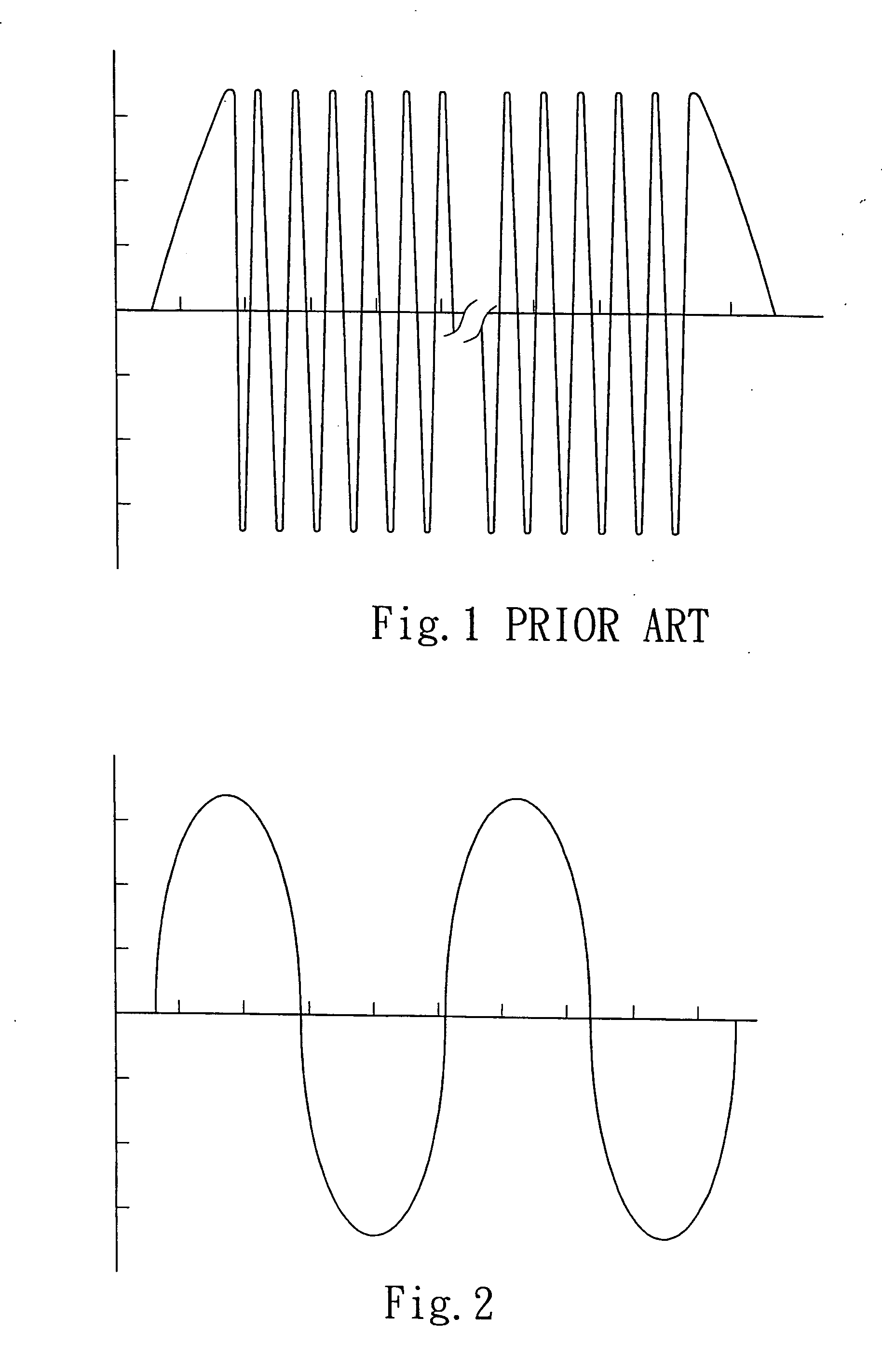
[0018] obtaining a lowest voltage and a highest voltage, wherein the inverter device is coupled to an external power source to receive the voltage cycles of an alternating current and obtains a lowest voltage and a highest voltage of the voltage cycles, and FIG. 2 illustrates the voltage waveform of an input alternating current in the prese...


PUM


Abstract

The present invention pertains to a method of determining a working voltage of an inverter, which utilizes a rectifying method to transform an alternating current into a pulse direct current, and then via a working frequency, divides a direct current cycle, which ranges in a lowest voltage—highest voltage—lowest voltage manner, into multiple continuous voltage pulses. The inverter receives each one of the multiple continuous voltage pulses and acts in response to each one of the multiple continuous voltage pulses and corresponding to the voltage cycle ranging between the lowest voltage and the highest voltage to output a variable voltage signal to a load. Thus, the working voltage of the inverter is analogous to the input voltage of the alternating current, and a power-factor regulating effect can be accomplished directly by the inverter.

Description

FIELD OF THE INVENTION [0001] The present invention relates to a method of determining a working voltage of an inverter, particular to the working voltage whereby a power-factor regulating effect can be accomplished without utilizing a power-factor regulator. BACKGROUND OF THE INVENTION [0002] Most of the loads, coupled to a general alternating current distribution system, comprise resistive and inductive components, except the purely resistive loads such as an incandescent lamp or an electric stove. Therefore, the current phase angle of electric lines will lag behind the voltage. Generally, The total current, supplied through power transmission lines and distribution lines by a power company's generator, can be resolved into an active current part and a reactive current part according to the rated voltage of each load. The kilowatt-hour meter in the user end only records the active power. However, the reactive power will incur a line drop and a line loss. It's the loss both for the...

Claims


Application Information

Patent Timeline
IPC IPC(8): H05B41/36
CPCG01R21/006G01R19/16538
Inventor CHOU, CHIN-WEN
Owner ZIPPY TECH
Why Eureka
Try Eureka