Tilt correction method detecting tilt with same linear velocity as upon actually recording/reproducing at each radial position
a correction method and tilt technology, applied in the direction of digital signal error detection/correction, instruments, recording signal processing, etc., can solve the problems of imposing a negative influence on recording/reproducing quality, deteriorating recording/reproduction quality, and troublesome recording/reproduction
- Summary
- Abstract
- Description
- Claims
- Application Information
AI Technical Summary
Benefits of technology
Problems solved by technology
Method used
Image
Examples
example 1
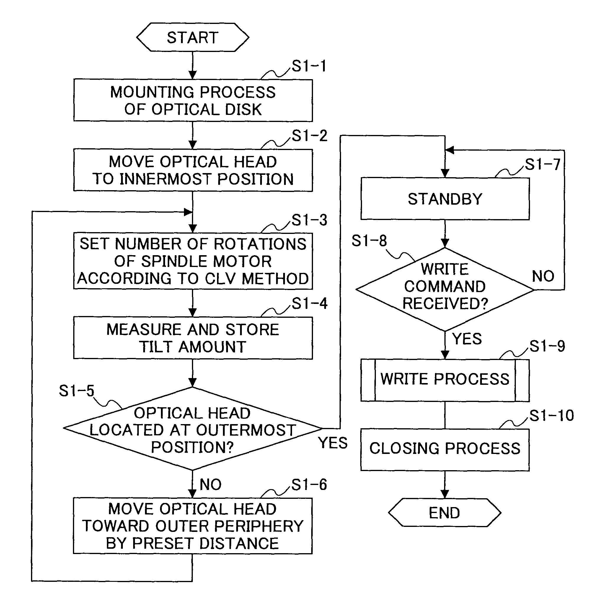
[0072]When the write command is received, the optical head is first moved to a write start position (S2-1) as shown in FIG. 7. Thereafter, a tilt amount at a tilt-amount measuring position nearest the write start position is read from the memory 24, and a tilt correction is performed according to the read tilt amount (S2-2), and thereafter, a recording is started (S2-3). During the recording, the position of the optical head is monitored (S2-4). When the optical head reaches the next tilt-amount measuring position (Y in S2-4), a tilt correction amount corresponding to the tilt-amount measuring position is read from the memory 24, and a tilt correction is performed according to the read tilt amount (S2-5). Then, when the recording is completed (Y in S2-6), the closing process follows the write process.
example 2
[0073]When the write command is received, the optical head is first moved to a write start position (S3-1) as shown in FIG. 8. Thereafter, a tilt amount at a tilt-amount measuring position nearest the write start position is read from the memory 24, and a tilt correction is performed according to the read tilt amount (S3-2), and thereafter, a recording is started (S3-3). During the recording, the position of the optical head is monitored. S3-1 to S3-3 in Example 2 are identical to S2-1 to S2-3 in Example 1. Then, it is judged whether the optical head reaches a middle point to the next tilt-amount measuring position (S3-4). When the optical head reaches the middle point (Y in S3-4), a tilt correction amount corresponding to the next tilt-amount measuring position is read from the memory 24, and a tilt correction is performed according to the read tilt amount (S3-5). Then, when the recording is completed (Y in S3-6), the closing process follows the write process.
example 3
[0074]When the write command is received, the optical head is first moved to a write start position (S4-1) as shown in FIG. 9. Thereafter, it is judged whether the present position of the optical head is a tilt-amount measuring position (S4-2). When the present position of the optical head is a tilt-amount measuring position (Y in S4-2), a tilt amount corresponding to the present position is read from the memory 24, and a tilt correction is performed according to the read tilt amount (S4-3). When the present position of the optical head is not a tilt-amount measuring position (N in S4-2), tilt amounts corresponding to tilt-amount measuring positions adjacent to the present position both inwardly and outwardly are read from the memory 24, and a tilt amount of the present position is calculated by a proportional calculation, and then, a tilt correction is performed according to the calculated tilt amount (S4-4).
[0075]Thus, after performing the tilt correction at the write start positi...
PUM
 Abstract
Description
Claims
Application Information
 - R&D
- Intellectual Property
- Life Sciences
- Materials
- Tech Scout
- Unparalleled Data Quality
- Higher Quality Content
- 60% Fewer Hallucinations
Browse by: Latest US Patents, China's latest patents, Technical Efficacy Thesaurus, Application Domain, Technology Topic, Popular Technical Reports.
© 2025 PatSnap. All rights reserved.Legal|Privacy policy|Modern Slavery Act Transparency Statement|Sitemap|About US| Contact US: help@patsnap.com


