Apparatus and method for estimating a plurality of channels

a plurality of channel technology, applied in the field of channel estimation, can solve the problems of enormous computational complexity at the receiver, new challenges in channel estimation, and the disclosed algorithm may not be suitable for mass-market mobile receivers, so as to simplify the channel estimation scheme, simplify the channel estimation procedure, and reduce complexity

Inactive Publication Date: 2008-02-05
NTT DOCOMO INC
View PDF2 Cites 215 Cited by
  • Summary
  • Abstract
  • Description
  • Claims
  • Application Information

AI Technical Summary

Benefits of technology

[0034]It is an object of the present invention to provide an improved concept for channel estimation with reduced complexity.

Problems solved by technology

This implies new challenges for channel estimation.
While the separation of the signals corresponding to several transmitting points, each of them having a transmit antenna, is a challenging task, the extension from a receiver having one antenna to a system with several receive antennas is straight forward, as long as the signals are mutually uncorrelated.
Although the pilot symbols described in the above-cited prior art allow an accurate channel estimation, an enormous computational complexity at the receiver is required in order to perform matrix inversions required by the channel estimation algorithm.
Due to this high computational complexity, the estimation scheme described in the above prior art document cannot be implemented at low cost, so that the disclosed algorithm may not be suitable for mass-market mobile receivers.
However, due to a difficulty of obtaining perfect orthogonality between training sequences, matrix inversions may be necessary.
Moreover, the channel estimation algorithm applied by Li has still a high complexity due to the required matrix by vector multiplications.
Hence, with an increasing number of transmit antennas, the complexity of the complicated estimation scheme proposed by Li rapidly increases due to the high number of complex valued multiplications.

Method used


Image

  • Apparatus and method for estimating a plurality of channels
  • Apparatus and method for estimating a plurality of channels
  • Apparatus and method for estimating a plurality of channels

Examples


Embodiment Construction

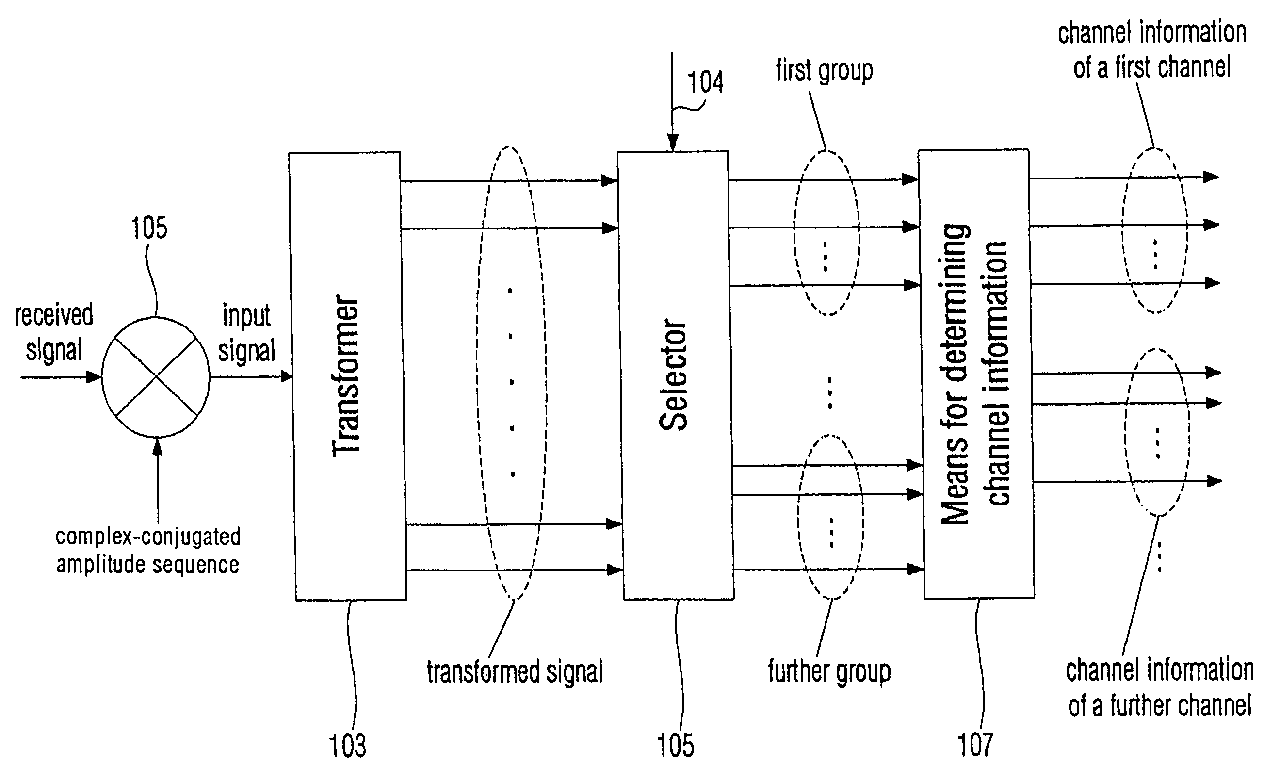
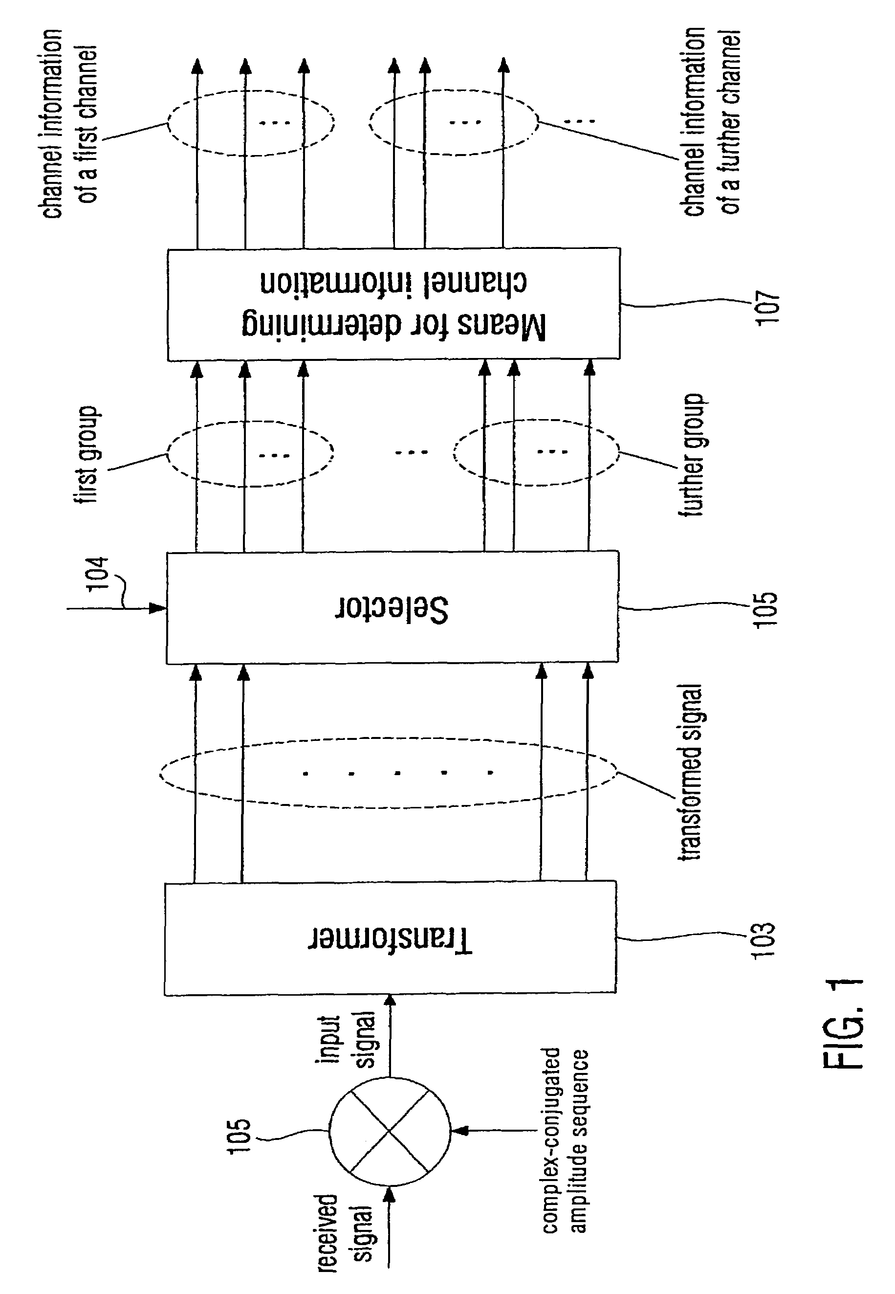
[0067]The apparatus shown in FIG. 1 comprises a multiplier 101 having two inputs and one output. The output of the multiplier 101 is connected to a transformer 103 having a plurality of outputs for providing a transformed signal. The plurality of outputs of the transformer 103 is connected to a selector 105 having a control input 104 providing a delay information for proper group selection. The selector 105 has a plurality of outputs, wherein a number of outputs is equal to a number of inputs of the selector 105 and, thus, equal to a number of outputs of the transformer 103. The plurality of outputs of the selector 105 is connected to a means 107 for determining channel information, the means 107 having a plurality of outputs.

[0068]The apparatus shown in FIG. 1 demonstrates the inventive low complexity channel estimation scheme based on pilot signals being orthogonal to each other within the predetermined orthogonality range and having a phase shift to each other. If the pilot seque...


PUM


Abstract

An apparatus for estimating a plurality of channels from a plurality of distinct transmitting points, wherein an input signal includes a super position of signals based on a first pilot sequence transmittable from a first transmitting point and on a second pilot sequence transmittable from a second transmitting point, the first pilot sequence and the second pilot sequence having a phase shift to each other, comprises a transformer, which is operative to translate phase shifts between the first and the second pilot sequence into a delay, so that a first group of a set of discrete values of the transformed signal includes channel information of a first channel and that a second group of a set of discrete values includes channel information of a second channel, a selector for selecting the first group from the set of discrete values and for selecting the second group from the set of discrete values to obtain selected groups, and means for determining channel information for the plurality of channels based on the selected groups. The selection of groups at the output of the transformer for obtaining channel information for the channel allows the construction of a simplified receiver.

Description

CROSS-REFERENCE TO RELATED APPLICATIONS[0001]This application is a continuation of co-pending International Application No. PCT / EP03 / 003211, filed Mar. 27, 2003, which designated the United States and was not published in English.BACKGROUND OF THE INVENTION[0002]1. Field of the Invention[0003]The present invention is in the field of telecommunications and, in particular, in the field of channel estimation in a multiple input scenario, in which a receiver receives signals from more than one transmitting antennas.[0004]2. Description of the Related Art[0005]The steadily-increasing demand for high data rates necessary for today's and future mobile radio applications require high data rate techniques efficiently exploiting the available band width or, in other words, the achievable channel capacity. Therefore, multiple input multiple output (MIMO) transmission systems have achieved considerable importance in recent years. MIMO systems employ a plurality of transmitting points, each of t...

Claims


Application Information

Patent Timeline
Patent Type & Authority Patents(United States)
IPC IPC(8): H04B7/10H04J99/00H04B1/707H04J11/00H04L1/06H04L25/02H04L27/26
CPCH04B7/0684H04L25/0204H04L25/0226H04B2201/70701H04L1/0618H04L27/2647
Inventor AUER, GUNTHER
Owner NTT DOCOMO INC
Why Eureka
Try Eureka