
Flexible connection device between a bogey side beam and an axle-box

a technology of flexible connection and side beam, which is applied in the directions of axle-box mounting, transportation and packaging, sustainable transportation, etc., can solve the problems of more difficult filtering, and achieve the effect of relatively low cost and weight saving

Active Publication Date: 2008-02-12
ALSTOM TRANSPORT TECH SAS
View PDF13 Cites 11 Cited by
  • Summary
  • Abstract
  • Description
  • Claims
  • Application Information

AI Technical Summary

Benefits of technology

[0004]The object of the present invention is to provide a connection device which absorbs forces in the manner of helical springs and which is compatible with spring blades, while also accommodating appreciable displacements between the parts it interconnects.
[0005]The flexible connection device of the invention is located between a flexible side beam of a bogey frame and an arm of an axle-box, wherein the stiffness of the connection is greater in the vertical direction (Z) than in the two horizontal directions (X, Y). This makes it possible to decouple the side beam from the axle-box and thus to reduce the stresses applied to the interfaces of those parts when the bogey frame moves transversely and vertically relative to the axles. This thus presents the advantage of allowing relative displacements between the axle-box and the side beam, which is flexible. This disposition makes it possible in particular to avoid transferring forces onto the spring blade in the Y direction, thereby avoiding damage to the structure of the frame.

Problems solved by technology

Furthermore, positioning this elastomer very far upstream stops solid noise, i.e. noise generated by solids, much further upstream than does a conventional suspension where the noise is not stopped until secondary damping or the secondary suspension which therefore involves many more parts and parts that are much bulkier and therefore more difficult to filter.

Method used


Image

  • Flexible connection device between a bogey side beam and an axle-box
  • Flexible connection device between a bogey side beam and an axle-box
  • Flexible connection device between a bogey side beam and an axle-box

Examples


Embodiment Construction

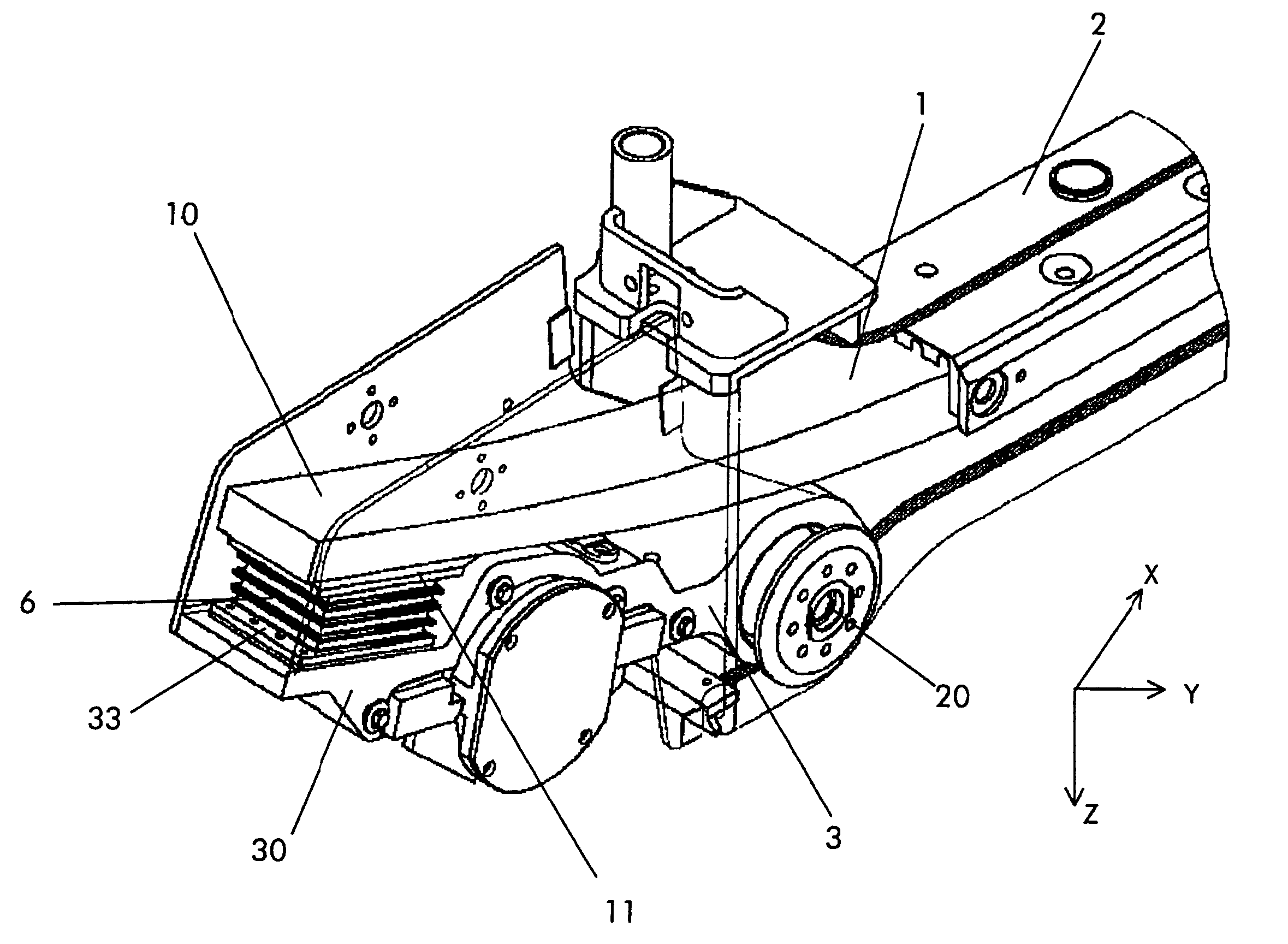
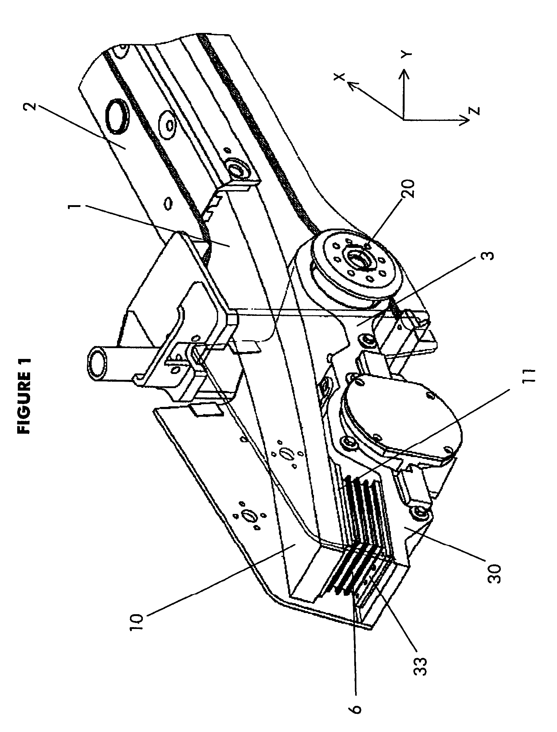
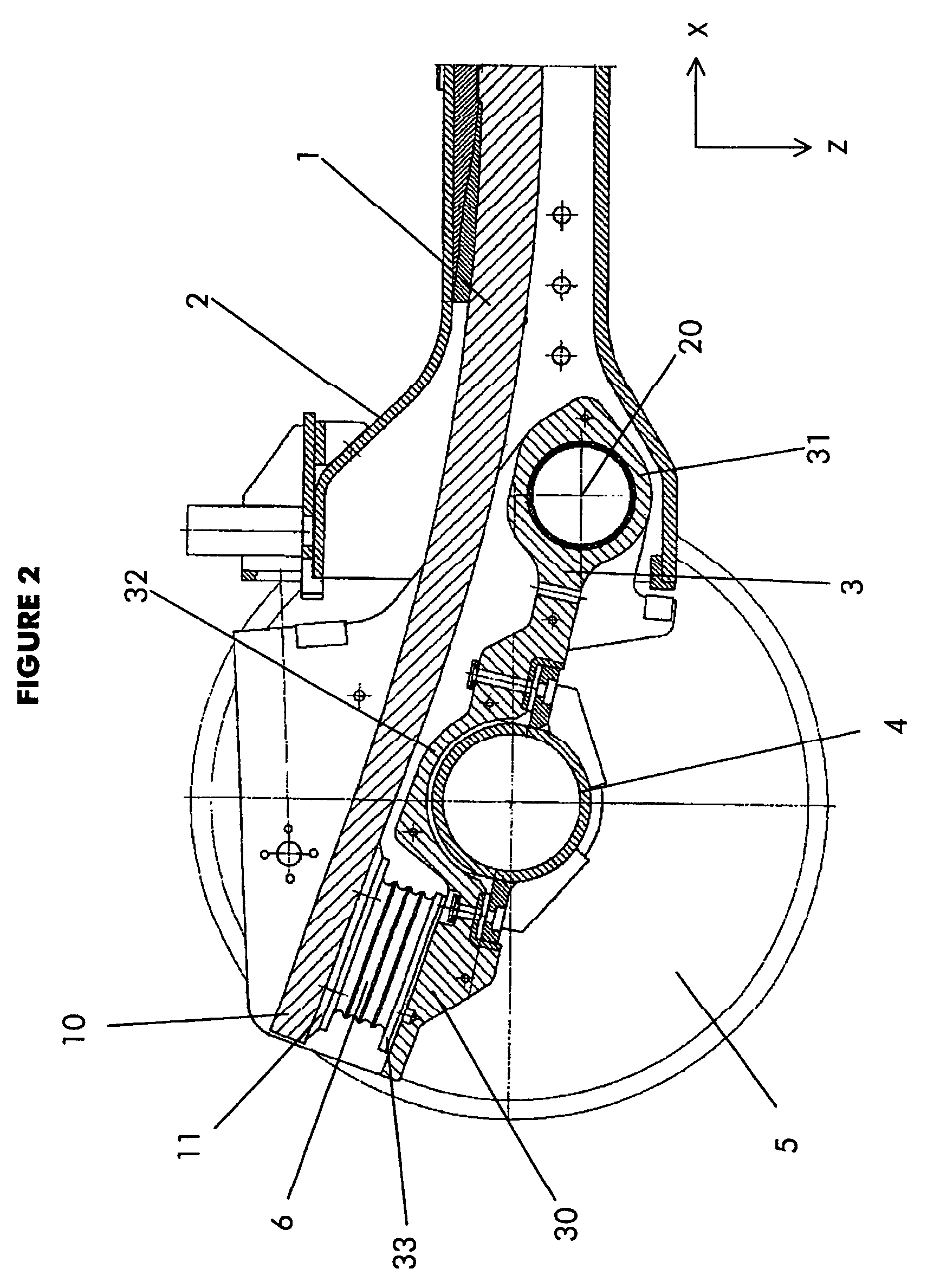
[0017]The bogey is symmetrical and comprises two side beams, constituted by resilient blades 1 in a structure 2, as can be seen in FIG. 1, with an axle-box 3 at each end of the bogey for supporting an axle 4 together with its pair of wheels 5.

[0018]A connection 6 is interposed between each blade 1 and the end 30 of the axle-box 3. This connection is made out of laminated elastomer in the example shown in the various figures.

[0019]The blade 1 is secured to the structure 2 by welding, bolting, or adhesive-bonding, or by any other technique known to the person skilled in the art.

[0020]The axle-box or arm-box 3 is hinged to the structure 2 about a pin 20 at one end 31 of the main core, with the axle 4 being connected conventionally to the axle-box 3 in an intermediate portion 32 of the core, while the connection is made to the opposite end 30 of the core. The main core is made up of portions 30, 31, and 32 and it is also referred to as the core of the arm-box.

[0021]The connection elemen...


PUM


Abstract

The flexible connection device of the invention is disposed between a flexible side beam of a bogey frame and an arm of an axle-box, and wherein the stiffness of the connection is greater in the vertical direction (Z) than in the two horizontal directions (X, Y). This enables the side beam to be decoupled from the axle-box, thereby reducing the stresses at the interfaces between these parts when the bogey frame moves transversely and vertically relative to the axles. This also presents the advantage of allowing relative displacements between the side beam and the axle-box.

Description

[0001]The present invention relates to rail vehicle bogeys, and more particularly to the connection between a bogey side beam and an axle-box.BACKGROUND OF THE INVENTION[0002]Conventionally, this connection is made by a helical spring coupled to a shock absorber which absorbs the shocks or displacements transmitted by the frame to the bogey structure. Nevertheless, that construction is heavy and penalizes the performance of bogeys fitted therewith.[0003]Direct connections are also known between the axle and the side beam (and not the axle-box) implemented by metal or composite spring blades replacing conventional side beams. However, although blades of that type withstand bending well, they do not allow for transverse displacements which are therefore transmitted directly to the frame which can lead to wear of the fastenings and to risks of breakage, and reduces the lifetime of bogeys of that type.OBJECTS AND SUMMARY OF THE INVENTION[0004]The object of the present invention is to pr...

Claims


Application Information

Patent Timeline
Patent Type & Authority Patents(United States)
IPC IPC(8): B61F5/26B61F5/30B61F5/32B61F5/52
CPCB61F5/305B61F5/325B61F5/523Y02T30/38Y02T30/00
Inventor LANDROT, ALAIN
Owner ALSTOM TRANSPORT TECH SAS
Learn More