Wind turbine rotor

a wind turbine and rotor technology, applied in the field of wind turbine rotors, can solve the problems of deformation of the pitch bearing, the deformation of the gear meshing (and the bearing) of such systems, and the increase of weight and cost to the design, so as to avoid the deformation of the bearing, reduce the amount of gear material used, and reduce the cost

Active Publication Date: 2014-01-14
GE RENEWABLE TECH WIND BV
View PDF9 Cites 10 Cited by
  • Summary
  • Abstract
  • Description
  • Claims
  • Application Information

AI Technical Summary

Benefits of technology

[0010]According to this aspect, the pitch bearing comprises a reinforcement, which may be radially fixed to the inner side of the inner bearing ring thus increasing the radial stiffness of the bearing on the bearing ring on which the blade is fixed. At the same time, such a reinforcement enhances the stiffness of the connection between the blade and the bearing. The stiffness conferred by this reinforcement favours a proper contact between rolling elements and raceways machined in the bearing's rings. The reinforcement disc may thus improve the reliability and durability of an electromechanical pitch bearing.
[0012]In such a substantially integral piece, the reinforcement disc may absorb internal tensions and may transform them into a homogeneous tension distributed all through its surface. The reinforcement disc may thus allow different gear designs without distorting the loads acting on the bearing, i.e. avoiding deformation of the bearing.
[0013]In some embodiments, the reinforcement disc may be made of a different material than that of the inner and outer bearing rings, for example a cheaper material. The reinforced bearing may thus be cost-effective.
[0014]In some embodiments, the gear may cover substantially the whole inner or outer side of the inner or outer bearing ring. In others, it may cover a portion of the inner or outer side of the inner or outer bearing ring. This may substantially reduce the amount of gear material used.
[0015]In some embodiments, the gear or gear portions may be axially screwed to the reinforcement disc. This way, if necessary, the gear or gear portions may be easily repaired and / or replaced. Further, such axial screwing may be easily accessible from an inside portion of the hub.

Problems solved by technology

This way, some of the rolling elements of the bearing may carry larger loads than others, thus deforming the pitch bearing.
The loads acting on the bearing may cause the linear contact and load transmission between the driven gear (crown) and the drive pinion to be shifted from its nominal position and the gear meshing (and the bearing) of such systems may thus suffer deformations.
However, this would add weight and cost to the design.
But this kind of solution can be rather complicated and expensive.

Method used


Image

  • Wind turbine rotor
  • Wind turbine rotor
  • Wind turbine rotor

Examples


Embodiment Construction

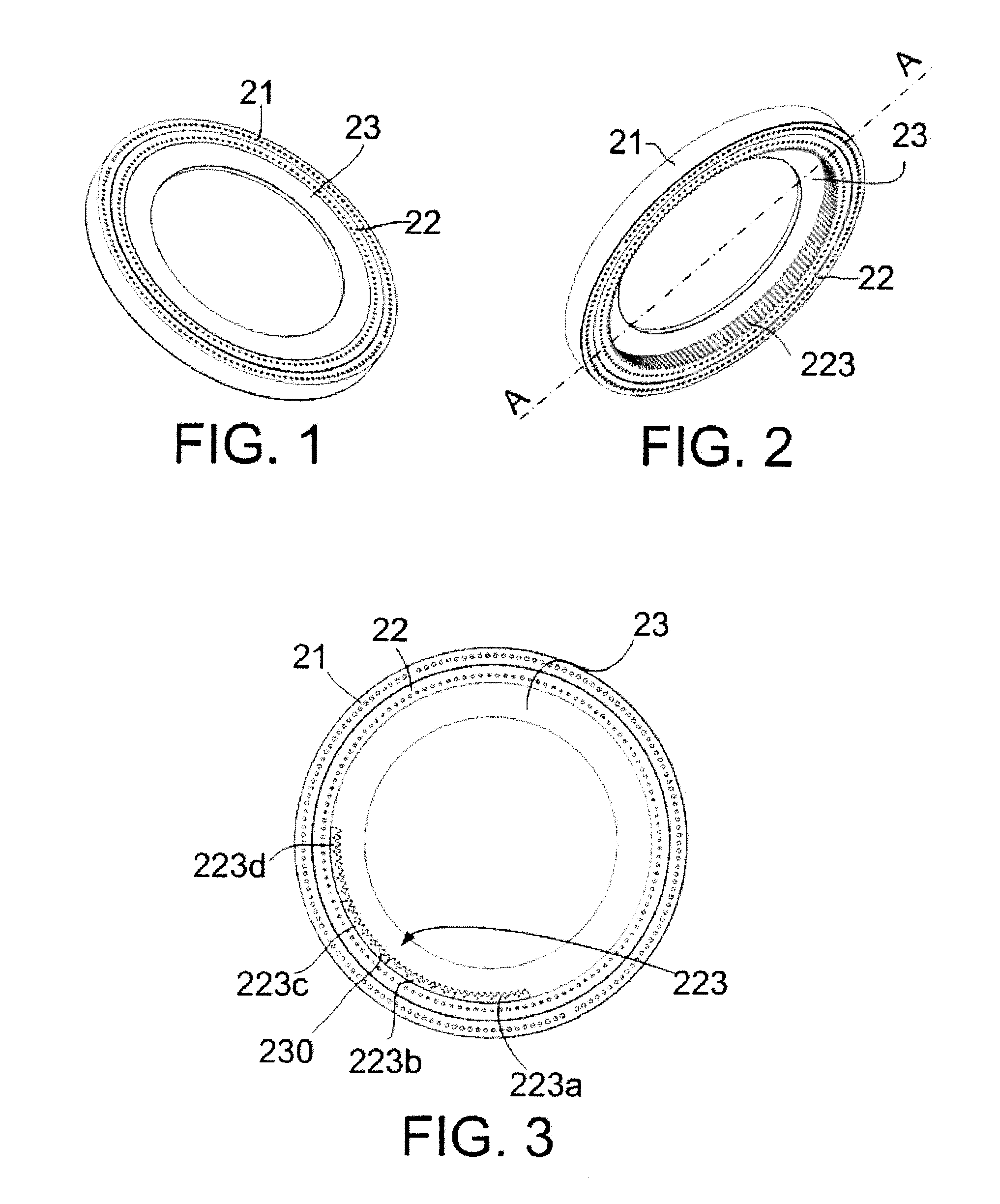
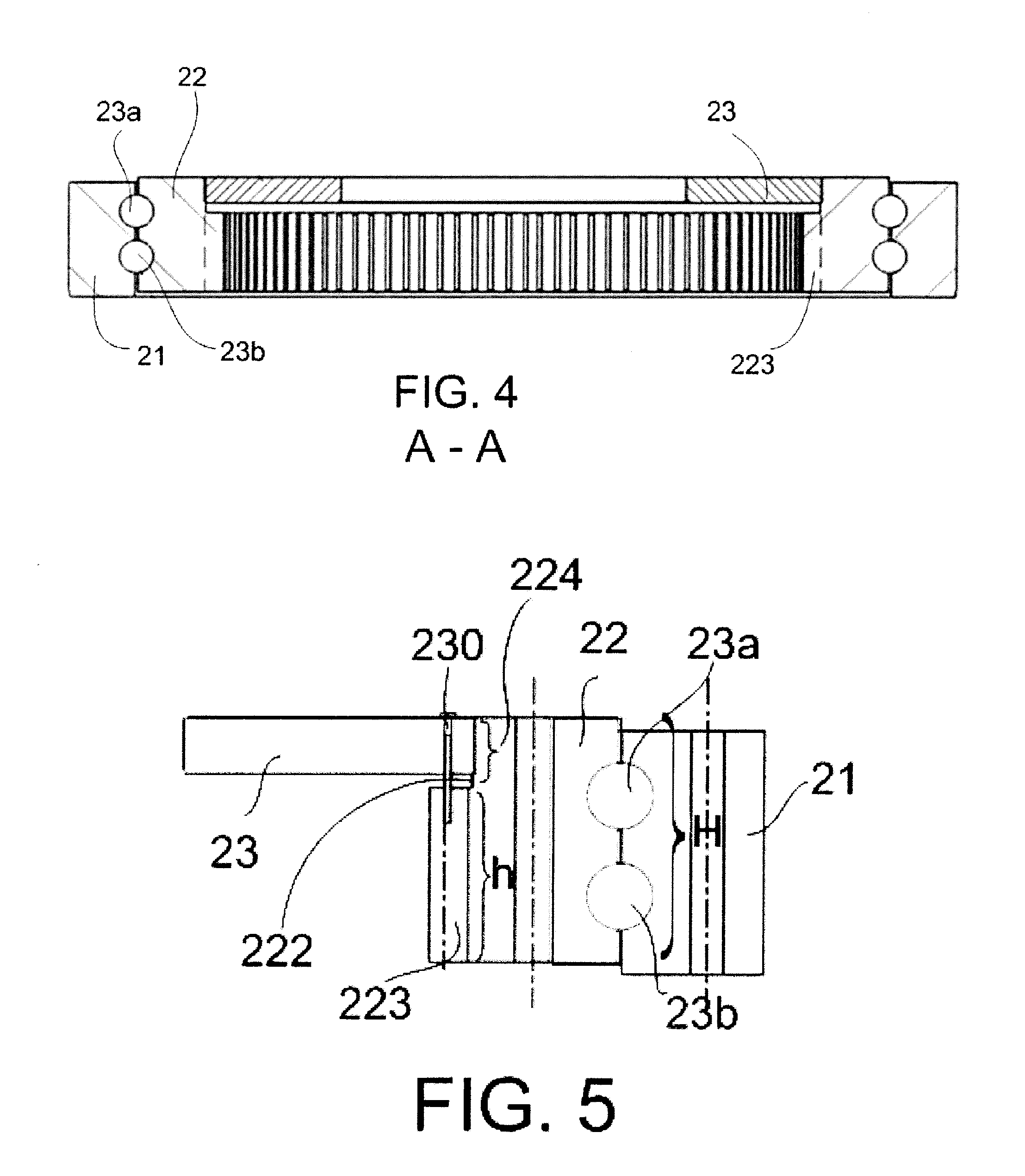
[0035]FIG. 1 shows a perspective top view, of a bearing according to a first embodiment. FIG. 2 shows a perspective bottom view of the same embodiment.

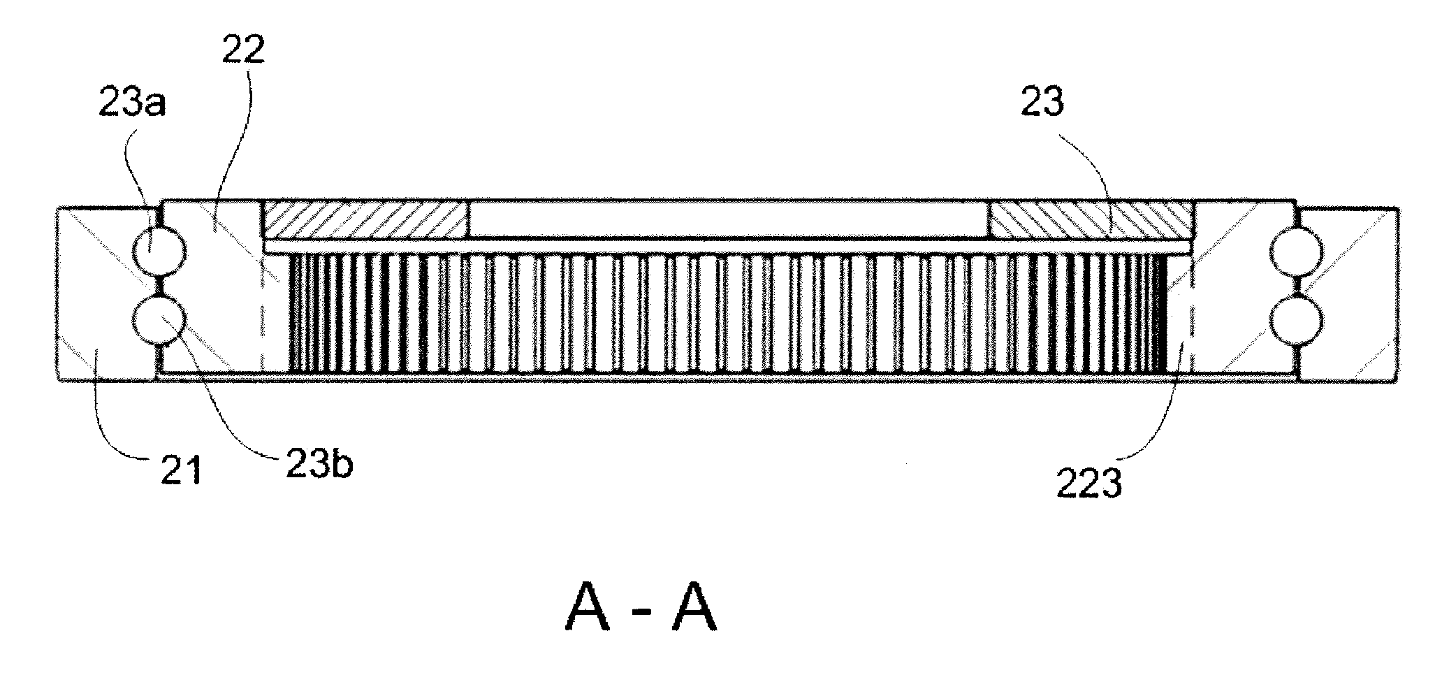
[0036]The bearing may comprise an outer bearing ring 21, an inner bearing ring 22 having an inner side (reference 222 of FIG. 5) and, between these two bearing rings, one or more rows of rolling elements (see also FIGS. 4 and 5) which may allow both bearing rings to rotate relative to each other. The bearing may further comprise a gear 223 which may mesh with a drive pinion of a drive motor (neither shown). Further, a reinforcement ring 23 may be radially fixed to the inner side of the inner bearing ring 22.

[0037]In an alternative embodiment the reinforcement ring may be a circular disc. In such cases the disc may comprise a central opening connecting an inside portion of the blade root with an inside portion of the hub.

[0038]FIG. 2 shows an embodiment wherein the gear 223 may cover the whole inner side of the inner bearing ring 22. I...


PUM

PropertyMeasurementUnit
angleaaaaaaaaaa
angleaaaaaaaaaa
outer diameteraaaaaaaaaa

Abstract

Wind turbine rotor comprising a hub, a plurality of blades and at least one pitch system for rotating a blade substantially along its longitudinal axis, the pitch system comprising a motor, a drive pinion, a gear arranged to mesh with the drive pinion and a pitch bearing, the pitch bearing comprising an outer bearing ring connected to the hub, an inner bearing ring connected to a blade and, between these two bearing rings, one or more rows of rolling elements which allow both bearing rings to rotate relative to each other, wherein the inner bearing ring has an inner side, and wherein a reinforcement disc is radially fixed to the inner side of the inner bearing ring.

Description

[0001]This application claims the benefit of European Patent Application EP 11382235.7 filed on Jul. 13, 2011 and U.S. Provisional Patent Application Ser. No 61 / 534,028 filed on Sep. 13, 2011.[0002]The present invention relates to wind turbine rotors, and more particularly relates to wind turbine rotors comprising at least one electromechanical pitch mechanism. The invention further relates to a wind turbine comprising the same and to a method of manufacturing a pitch bearing for such wind turbine rotors.BACKGROUND ART[0003]Modern wind turbines are commonly used to supply electricity into the electrical grid. Wind turbines generally comprise a rotor with a rotor hub and a plurality of blades. The rotor is set into rotation under the influence of the wind on the blades. The rotation of the rotor shaft drives the generator rotor either directly (“directly driven”) or through the use of a gearbox.[0004]An important auxiliary system generally provided on wind turbines is the pitch syste...

Claims


Application Information

Patent Timeline
Patent Type & Authority Patents(United States)
IPC IPC(8): F03D7/02
CPCF03D1/0658B23P11/00Y02E10/721F03D11/0008F05B2230/40F05B2230/60F03D7/0224Y02E10/722F05B2260/79F03D80/70Y10T29/49826Y02E10/72Y02P70/50
Inventor PASQUET, PIERRE
Owner GE RENEWABLE TECH WIND BV
Why Eureka
Try Eureka