
Fan selection method and fan selection device

a fan selection and fan selection technology, applied in fluid pressure control, process and machine control, instruments, etc., can solve the problems of fan selection error, no particular consideration of the size of the air vent at the housing, and complicated computation

Active Publication Date: 2008-02-12
SANYO DENKI CO LTD
View PDF3 Cites 4 Cited by
  • Summary
  • Abstract
  • Description
  • Claims
  • Application Information

AI Technical Summary

Benefits of technology

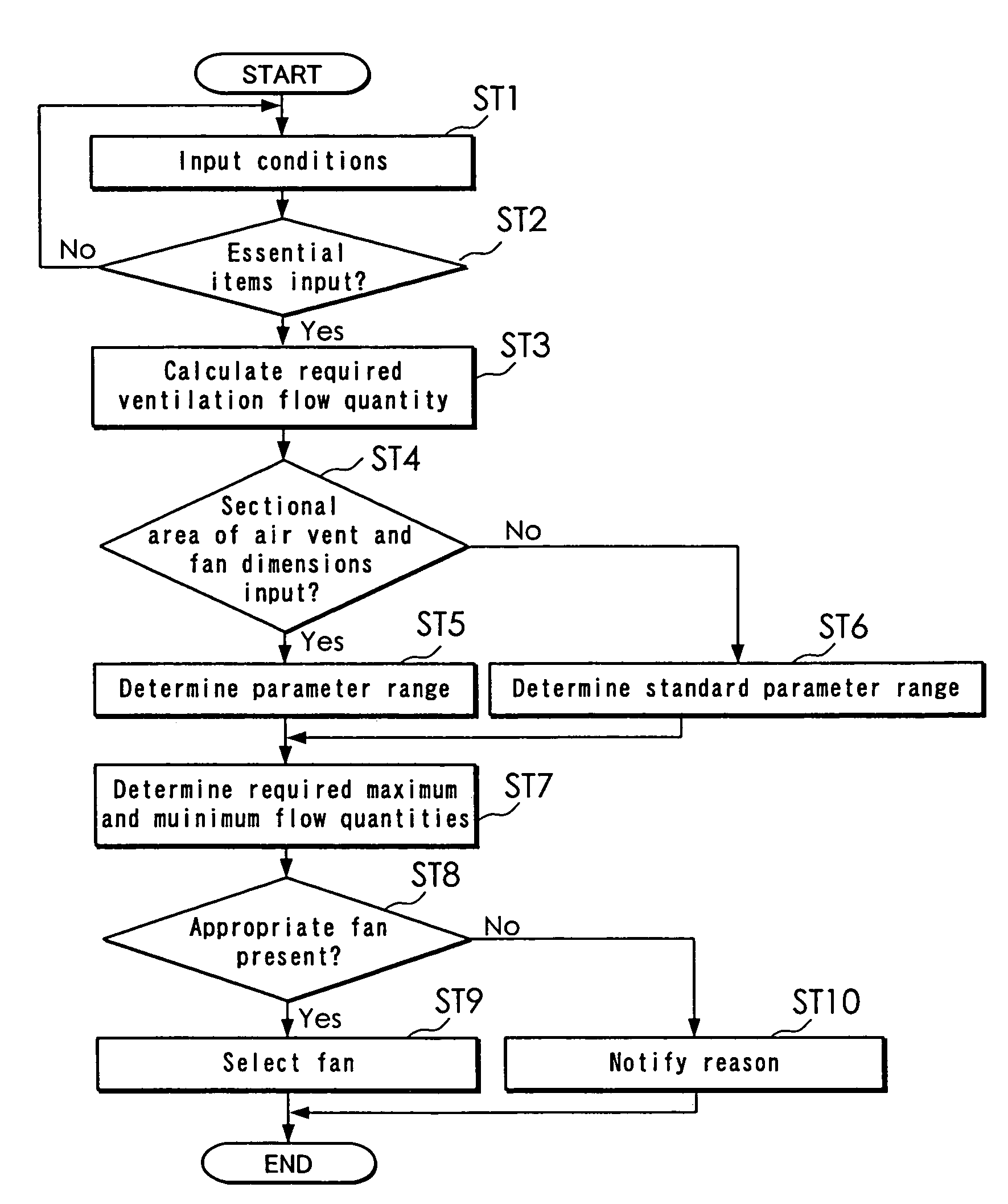
The present invention provides a method and device for selecting a fan for cooling an electric device using a small amount of data and simple computations. The method involves preparing parameter data and a database of fan data, determining the effective flow quantity ratio of the fan when the air vent is changed, and selecting the fan with the maximum flow quantity that falls between the required minimum and maximum flow quantities. The method can be easily performed even when the housing structure of the electric device is not known. The device can select a fan even under insufficient conditions. The method and device can be used in a variety of fan selection scenarios.

Problems solved by technology

In the conventional technique, however, no particular consideration is given to the size of the air vent at the housing.
Thus, a housing structure difference may cause an error in the fan selection.
Further, specifically, a rather complicated computation such as the computation for obtaining the impedance curve for the electric device including each of the fans is required.
As described above, in the conventional technique, the data on the fans must be prepared in advance in detail, and it needs time and effort to perform inputting or updating of the fan data.
Further, since the complicated computation is necessary for the fan selection and plotting the PQ curves, output curves, and impedance curve, the fan selection cannot be performed readily.
In the conventional technique, unless some conditions about the fan selection have been determined, the fan selection cannot be performed readily.

Method used


Image

  • Fan selection method and fan selection device
  • Fan selection method and fan selection device
  • Fan selection method and fan selection device

Examples


Embodiment Construction

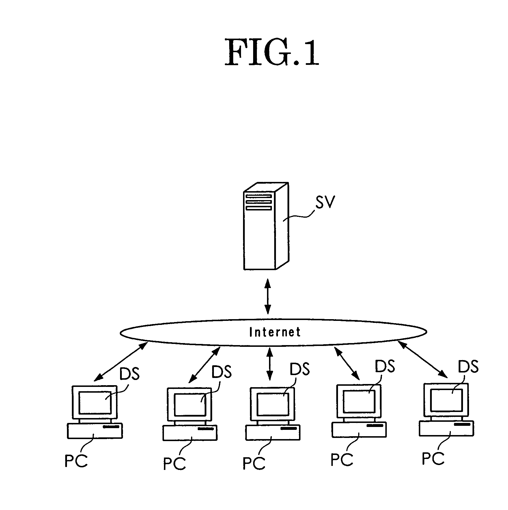
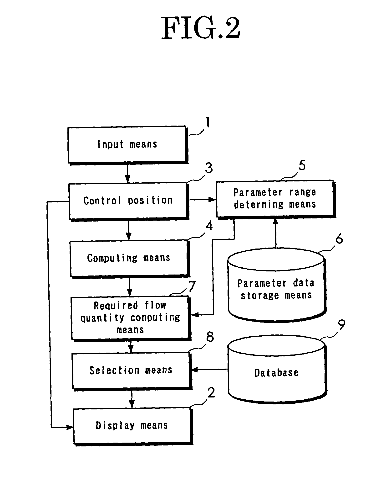
[0032]An embodiment of the present invention will be described below in detail with reference to drawings. FIG. 1 shows a configuration when a fan selection device of the present invention for carrying out a method of the present invention is implemented using a personal computer PC of each client connected to a network as a terminal device. Inside a server SV, a main portion of the fan selection device of the present invention for carrying out the method of the present invention is included. FIG. 2 is a block diagram showing a configuration of the embodiment in which the personal computer PC as the terminal device is used as input means 1 such as a keyboard and a mouse that are not shown and display means 2 constituted by a display DS, and other means are constructed within the server SV. The personal computer PC makes access to the server SV, thereby performing required screen display on the display means 2 constituted by the display DS. Within the server SV, a control portion 3, ...


PUM


Abstract

To provide a fan selection device capable of selecting a fan using a small amount data prepared in advance and also using simple computations. A required ventilation flow quantity is computed by computing means 4 when predicted total electric power consumption and a predicted air temperature rise are entered into a predetermined computational expression. Parameter range determining means 5 determines a parameter range of a proper flow quantity ratio necessary for cooling. Required flow quantity computing means 7 computes a minimum required flow quantity and a maximum required flow quantity by dividing the required ventilation flow quantity by the upper and lower limit values of the parameter range of the proper flow quantity ratio, respectively. Selection means 8 searches for a fan that produces the maximum flow quantity necessary for obtaining a flow quantity that falls between the minimum required flow quantity and the maximum required flow quantity, from a database 9, and selects the fan as the required fan.

Description

BACKGROUND OF THE INVENTION[0001]The present invention relates to a fan selection method and a fan selection device for selecting a fan required for use in cooling an inside space of a housing with an electric device that generates heat included therein.[0002]Japanese Patent Application Laid-Open Publication No. 246728 / 2004 discloses a method and a system for computing a proper level of each of a plurality of fans having different performances when mounted in an electronic device based on fan data, and determining ranking of fan candidates to be mounted in the electronic device based on a parameter for each of the fans obtained by this computation. Specifically, specifications covering an amount of heat in a heating element within the electronic device, an allowable temperature rise value of a housing that includes the electronic device, and the like are first determined. Next, a required flow quantity of the fan for cooling an internal temperature of the housing to within an allowa...

Claims


Application Information

Patent Timeline
Patent Type & Authority Patents(United States)
IPC IPC(8): G06F19/00G05D23/00G05D16/00F04D17/00F04D19/00F04D25/00F04D27/00G06F17/50H05K7/20
CPCF04D27/00H05K7/20209
Inventor KATO, AKIRAITO, KINSHI
Owner SANYO DENKI CO LTD
Learn More