
Device for indicating a beat level

a technology of a device and a level, which is applied in the direction of propellers, machine parts testing, structural/machine measurement, etc., can solve the problems of deteriorating the performance of various equipment installed in the vehicle, no means are provided for providing an indication of a level of vibration without, and no means are availabl

Active Publication Date: 2008-02-19
EUROCOPTER
View PDF10 Cites 4 Cited by
  • Summary
  • Abstract
  • Description
  • Claims
  • Application Information

AI Technical Summary

Benefits of technology

The present invention provides a device that can indicate a level of vibration in a rotary wing aircraft to assess equilibrium defects that cannot be detected by simple frequency analysis. The device includes an analyzer that responds to a reference frequency and a harmonic coefficient to extract the first and second acceleration signals. A control circuit receives the acceleration signals and produces the beat level. The device also includes a comparator that produces a warning signal if the beat level exceeds a predetermined threshold. The beat level is symptomatic of an anomaly on one or more of the moving members of the rotor and induces a virtual unbalance sensation in the cabin. The device is advantageous for maintaining vehicle integrity and ensuring safety for the crew and passengers of the helicopter. The evaluation signal can be taken from a vibration sensor or a speed of rotation sensor. The invention is particularly useful for helicopters with a rotor having a plurality of blades.

Problems solved by technology

Vibration may also degrade the performance of various items of equipment installed in the vehicle.
Nevertheless, at present, no means are provided for providing an indication of a level of vibration without being restricted to an identified frequency, i.e. no means are available that tend rather to take account of the overall behavior of the rotor.

Method used


Image

  • Device for indicating a beat level
  • Device for indicating a beat level

Examples


Embodiment Construction

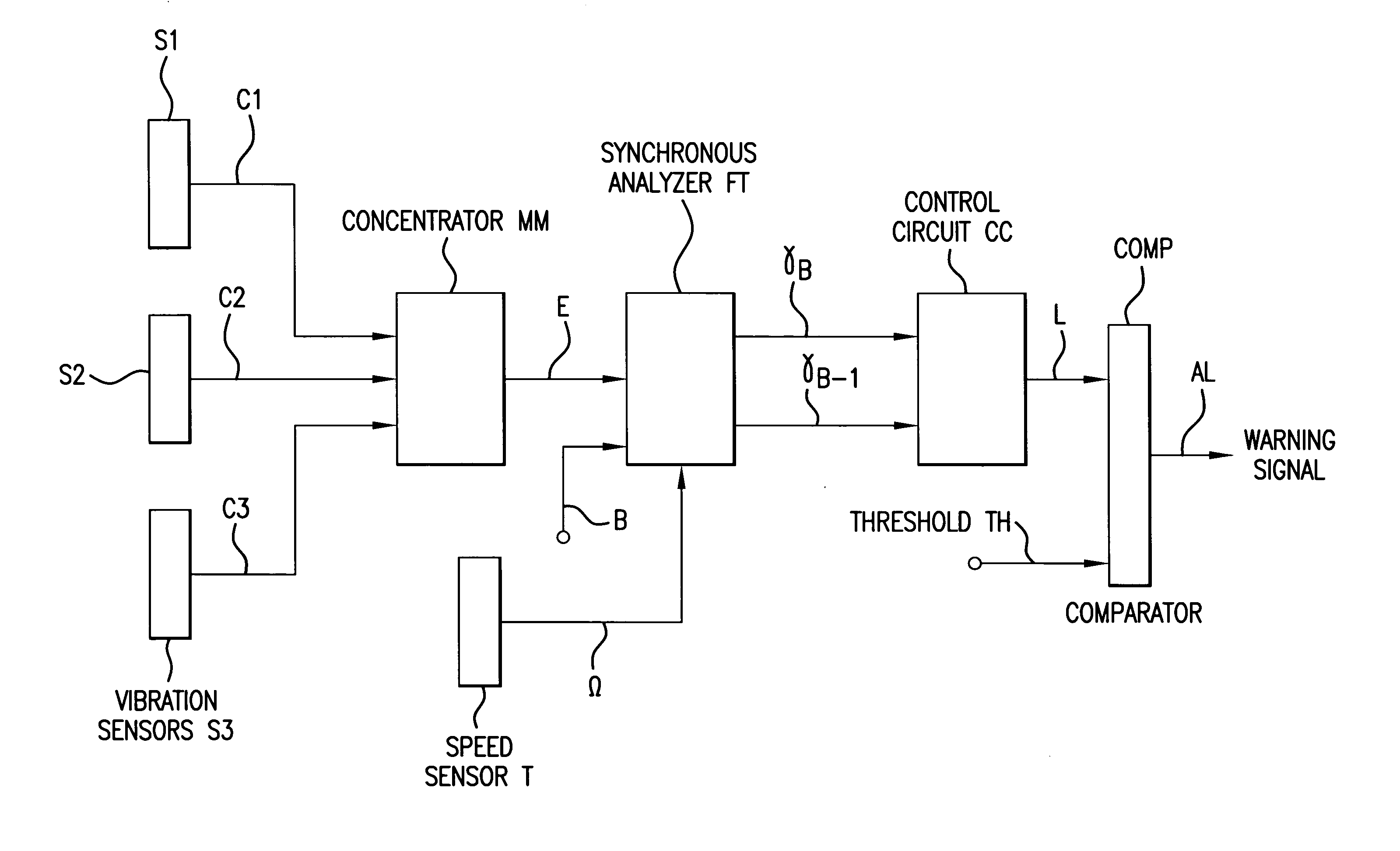
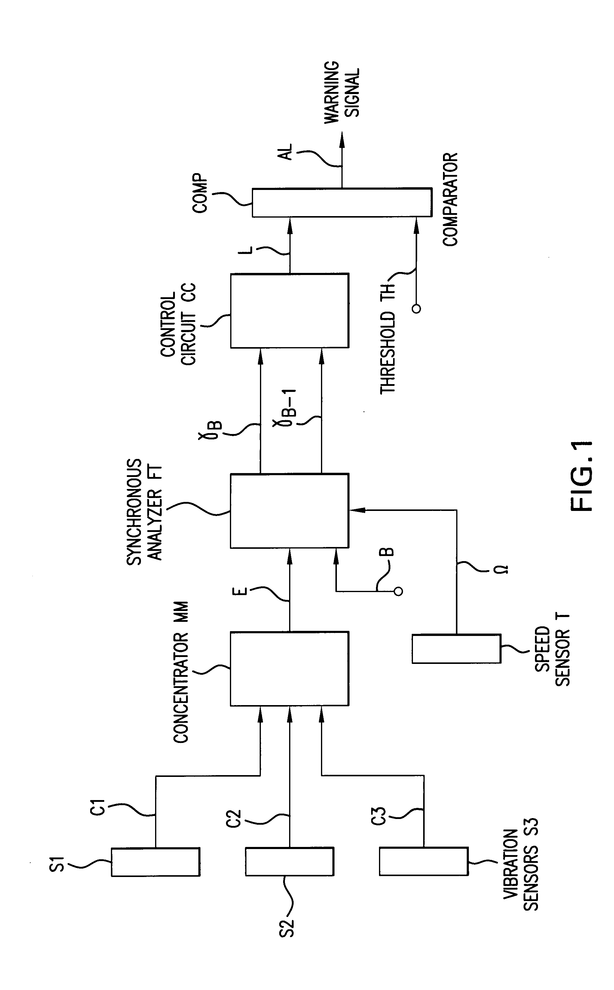
[0031]With reference to the figure, first, second, and third sensors S1, S2, and S3 are disposed in the cabin of a helicopter to measure vibration. These three sensors deliver respective first, second, and third measurement signals C1, C2, and C3 representing the acceleration to which each of them is subjected. The sensors are preferably accelerometers or strain gauges.

[0032]A concentrator member MM receives the three measurement signals C1, C2, and C3 in order to combine them (using some function) into an evaluation signal E.

[0033]In a first option, it sums the measurement signals.

[0034]In a second option, it takes as the evaluation signal, the greatest of the measurement signals.

[0035]It is appropriate to observe that the invention also applies when only one sensor is provided, in which case it delivers the evaluation E directly, and the concentrator member MM is omitted.

[0036]A tachometer T delivers the speed of rotation Ω of the main rotor of the helicopter.

[0037]Analyzer means ...


PUM


Abstract

A device for indicating a beat level L, the device including an analyzer which responds to a reference frequency Ω and a harmonic coefficient B to extract from an evaluation signal E a first acceleration signal γB at a frequency equal to the product of reference frequency Ω multiplied by harmonic coefficient B; and a second acceleration signal γB-1 at a frequency equal to the product of reference frequency Ω multiplied by the harmonic coefficient minus one; and it further includes a control circuit CC which receives acceleration signal γB, γB-1 to produce beat level L.

Description

[0001]The field of the invention is that of analyzing vibration within a vehicle, more particularly when the vehicle is provided with an engine driving a rotary propulsion member. A typical example of an application of the invention is a helicopter, a vehicle which presents a high level of vibration, essentially due to the main rotor which serves to provide both lift and propulsion.BACKGROUND OF THE INVENTION[0002]It is important to characterize the vibration present in such a vehicle, since the vibration is representative of stresses that lead to fatigue phenomena in various materials and that therefore have a direct influence on safety. Vibration may also degrade the performance of various items of equipment installed in the vehicle. In addition, vibration in the cabin of a helicopter determines the comfort of the passengers and of the pilot, and it goes without saying that pilot comfort is also an essential element for safety.[0003]A system is thus known for continuously recordin...

Claims


Application Information

Patent Timeline
Patent Type & Authority Patents(United States)
IPC IPC(8): G01M13/02G01M1/22B64C27/00
CPCB64C27/001G01H1/003G01H1/14
Inventor AUBOURG, PIERRE-ANTOINE
Owner EUROCOPTER
Learn More