Drill adapter for a power screwdriver

a technology of power screwdriver and drill adapter, which is applied in the direction of sleeve/socket joint, portable power-driven tools, turning apparatus, etc., can solve the problems of jamming and damage, and achieve the effect of wide application field and much easier handling

Inactive Publication Date: 2008-02-19
HILTI AG
View PDF13 Cites 29 Cited by
  • Summary
  • Abstract
  • Description
  • Claims
  • Application Information

AI Technical Summary

Benefits of technology

[0014]Upon mounting of the inventive drill adapter, the support region of the screwdriver is received in the receiving space of the push-on sleeve, and the axial stop, which is provided on actuation means, contacts the tool spindle. Only upon further advancing the drill adapter over the support region, the axial stop displaces the tool spindle in the mounting direction, with the spindle displacing the drive clutch members into engagement with each other. The push-on sleeve can be brought into engagement with the support region of the screwdriver only by the engagement bodies. Because the axial stop is axially offset relative to the push-on sleeve, the drive clutch is firmly and stably held in an engagement condition by the formlocking connection between the push-on sleeve and the screwdriver. In this way, with the mounted drill adapter, direct driving of the spindle is achieved. Thereby, the drill adapter can be conveniently used with screwdrivers having a normally separated, drive clutch.
[0027]Advantageously, the drive spindle has a drill receptacle, and the shank of the drive rod has a polygon cross-section dimensions and a shape of which are adapted to a receiving cross-section of the bit receptacle. This provides for a particularly good torque transmission.

Problems solved by technology

This is because a displaceable spindle in many cases leads to an uneven drilling of a workpiece, and a drill later can remain in a hole when the screwdriver is pulled out, which can lead to jamming and damage.

Method used


Image

  • Drill adapter for a power screwdriver
  • Drill adapter for a power screwdriver
  • Drill adapter for a power screwdriver

Examples


Embodiment Construction

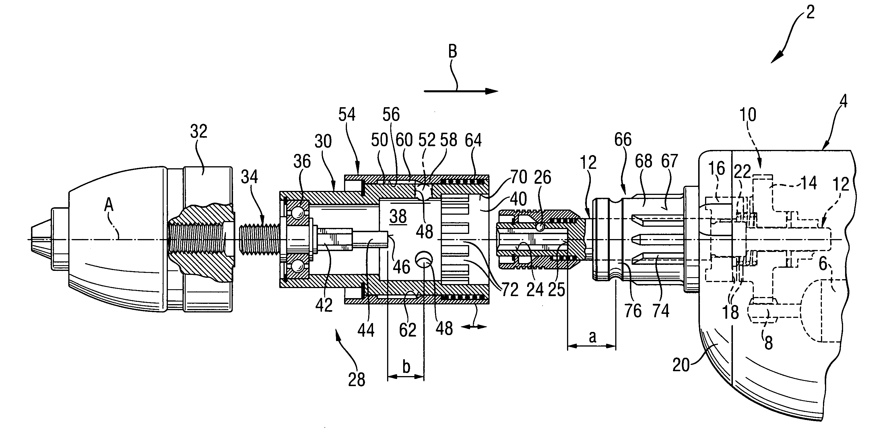
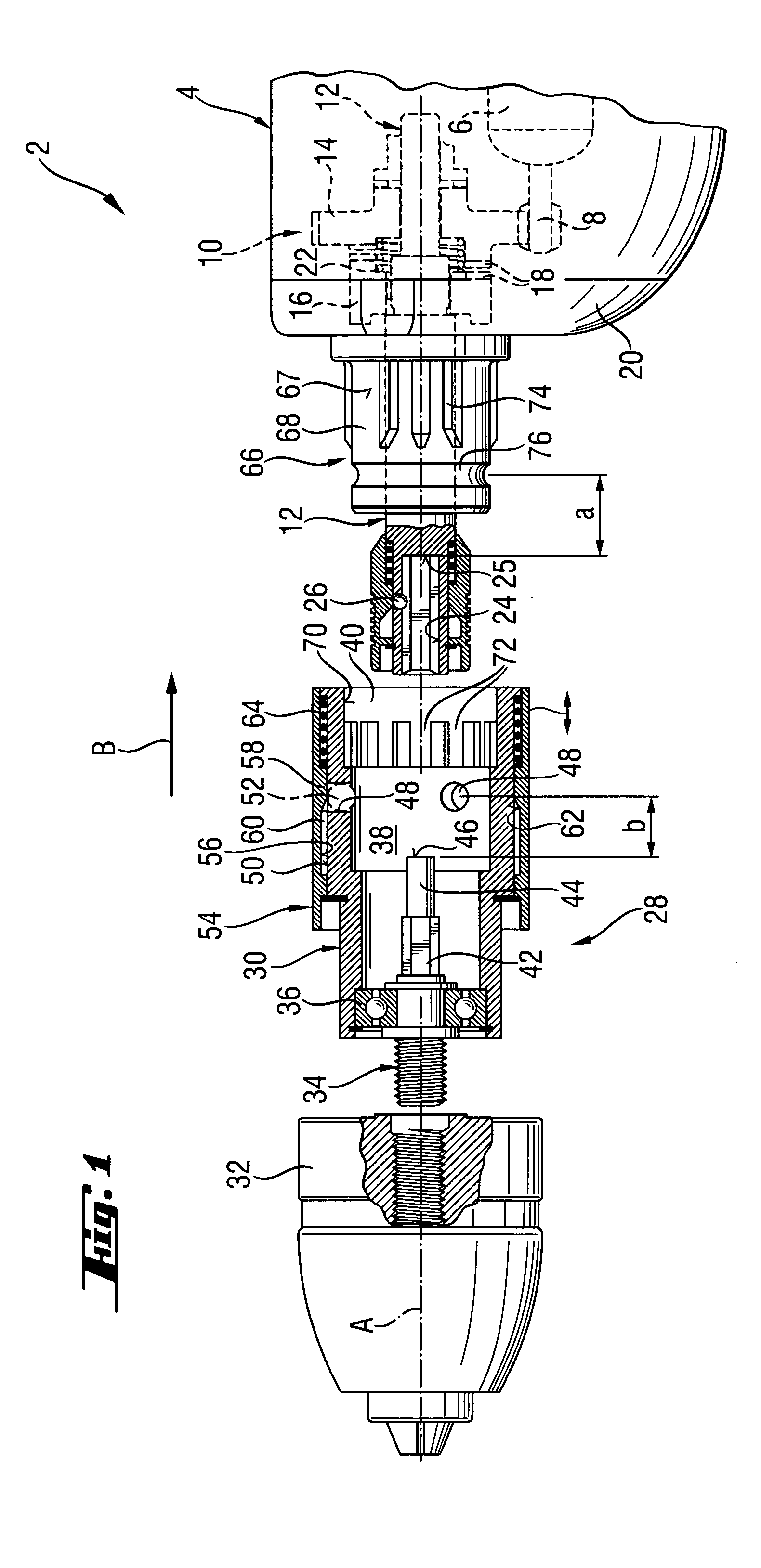
[0033]A drill adapter-power screwdriver assembly 2, which is shown in FIG. 1, includes a power screwdriver 4 which is formed as a constructional screwdriver with a tool side end relevant for the present invention an at which a tool bit (not shown) is mountable. The screwdriver 4 has a motor 6 which is shown with dash lines and which drives a tool spindle 12 via a driving pinion 8 and a drive clutch 10.

[0034]The drive clutch 10 has a first clutch member 14 rotably supported on the tool spindle 12 and cooperating with the driving pinion 8, and a second clutch member 16 fixedly connected with the tool spindle 12 for joint rotation therewith. Both clutch members 14 and 16 have claws 18 which, upon displacement of the second clutch member 16 toward and away from the first clutch member 14, are brought into engagement with each other. To this end, the tool spindle 12 is displaceably arranged in the housing 20 of the screwdriver 4. For disengagement of the drive clutch 10 in its normal, i....


PUM

PropertyMeasurementUnit
axial distanceaaaaaaaaaa
torqueaaaaaaaaaa

Abstract

A drill adapter for a power screwdriver and including a locking device for releasably securing the drill adapter (28) on the support region (66) of the screwdriver (4) and having a push-on sleeve (30) supportable on the support region (66) and at least one engagement member (52) for releasably securing the push-on sleeve (30) on the support region, and an element for actuating the drive clutch (10) of the screwdriver (4) via the tool spindle (12) and projecting into a receiving space (38), which is partially limited by the push-on sleeve (30) and is open at one side, and having an axial stop (46) for engaging the tool spindle (12), with the at least one engagement member (52) projecting, in its locking position, beyond an inner surface (70) of the push-on sleeve (30) for establishing an axial formlocking connection between the push-on sleeve (30) and the support region (66) of the screwdriver (4) and which provides for actuation of the drive clutch (10) with actuating element.

Description

BACKGROUND OF THE INVENTION[0001]1. Field of the Invention[0002]The present invention relates to a drill adapter for a power screwdriver and having a locking device for releasably securing the drill adapter on the support region of the screwdriver and including a push-on sleeve supportable on the support region of the screwdriver and attachment means having a locking position in which the drill adapter is secured on the support region, and a release position in which the drill adapter can be mounted on or dismounted from the support region, with the attachment means having at least one engagement member supported in the push-on sleeve, a drill chuck for receiving a drilling tool and rotatable relative to the locking device and torque transmitting means for drivingly connecting the drill chuck with the tool spindle of the screwdriver.[0003]2. Description of the Prior Art[0004]Drill adapters of the type described above are used for expanding the function field of a pure screwdriver so...

Claims


Application Information

Patent Timeline
Patent Type & Authority Patents(United States)
IPC IPC(8): B23B51/08B23B45/00B23B51/12B25B21/00B25F3/00
CPCB25B21/007Y10T279/3418Y10T408/957B25F3/00
Inventor HOFBRUCKER, THOMASBADER, THOMAS
Owner HILTI AG
Why Eureka
Try Eureka