Blower

a blower and blower technology, applied in the field of blowers, can solve the problems of poor ventilation efficiency and increase in noise, and achieve the effects of improving ventilation efficiency, increasing static pressure, and reducing nois

Inactive Publication Date: 2008-02-19
MITSUBISHI ELECTRIC CORP
View PDF9 Cites 11 Cited by
  • Summary
  • Abstract
  • Description
  • Claims
  • Application Information

AI Technical Summary

Benefits of technology

[0005]This invention has been made with a view toward solving the above problems. It is an object of this invention to provide a blower in which an improvement in ventilation efficiency is achieved through an increase in static pressure, etc. and in which it is possible to achieve a reduction in noise.

Problems solved by technology

Thus, in its outer peripheral portion, the effect of mixed flow due to the blade profile is rather small, with the result that a sufficient increase in static pressure cannot be achieved, leading to poor ventilation efficiency, an increase in noise, etc.

Method used


Image

  • Blower
  • Blower
  • Blower

Examples


embodiment 1

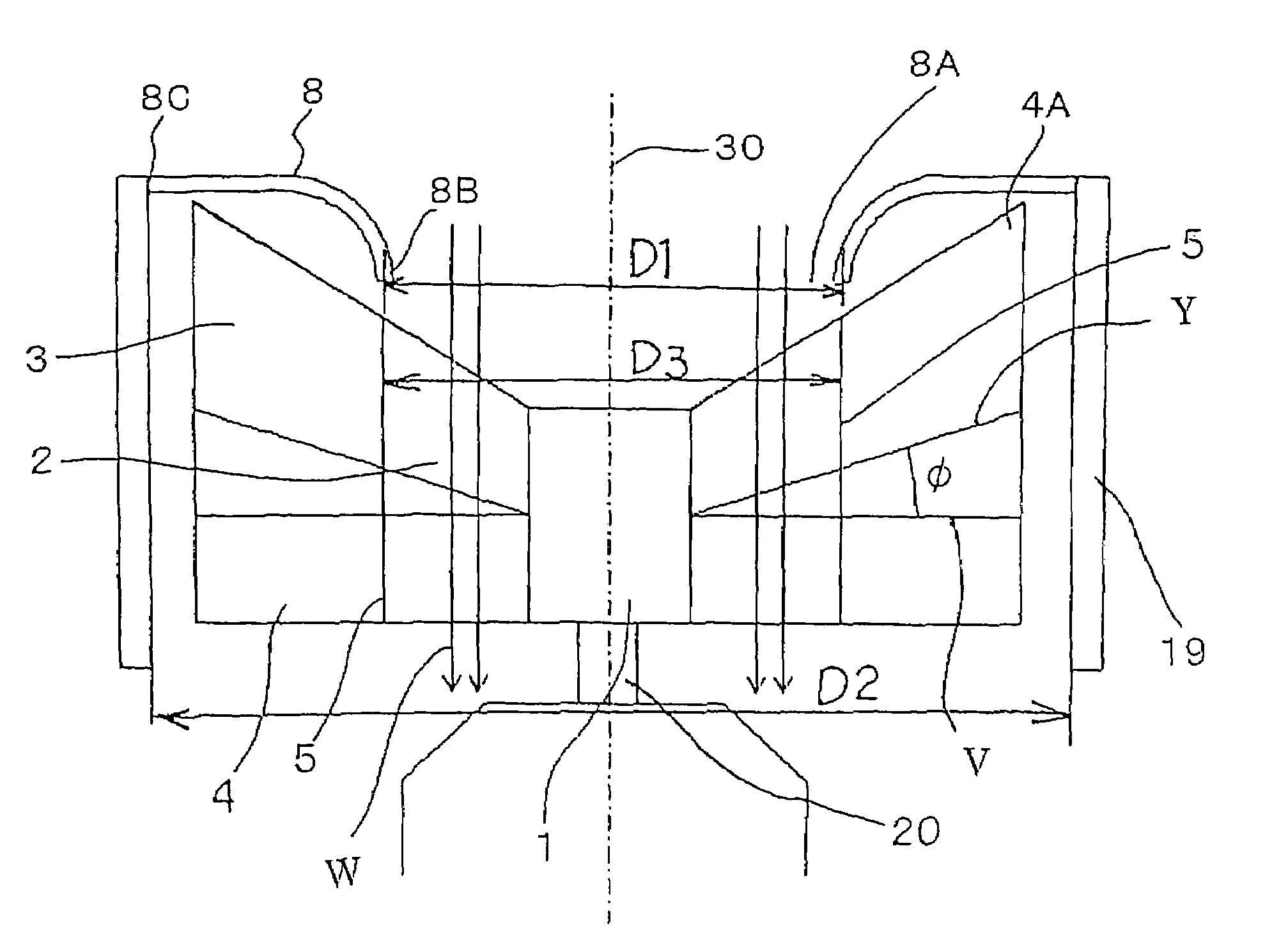
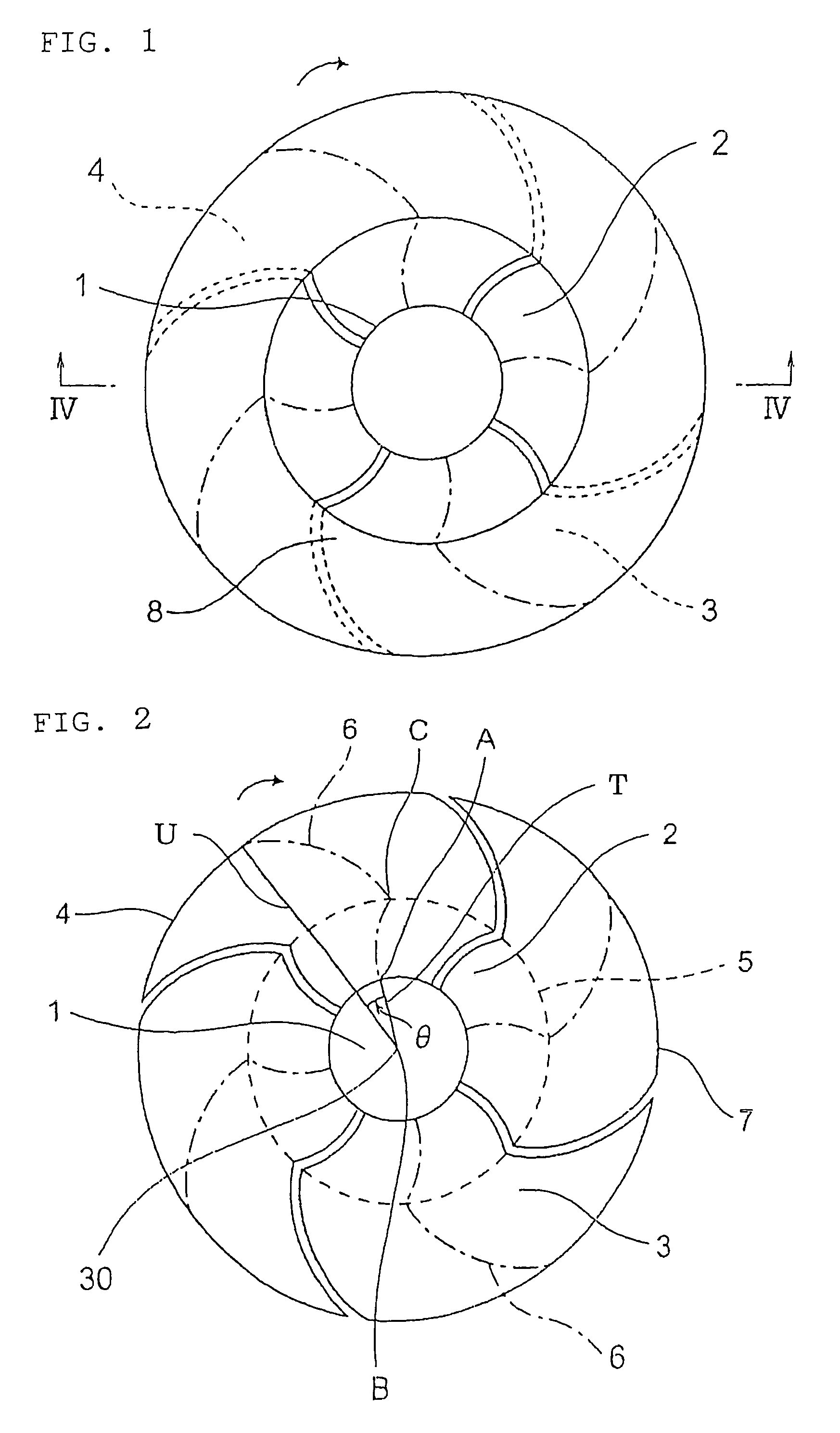
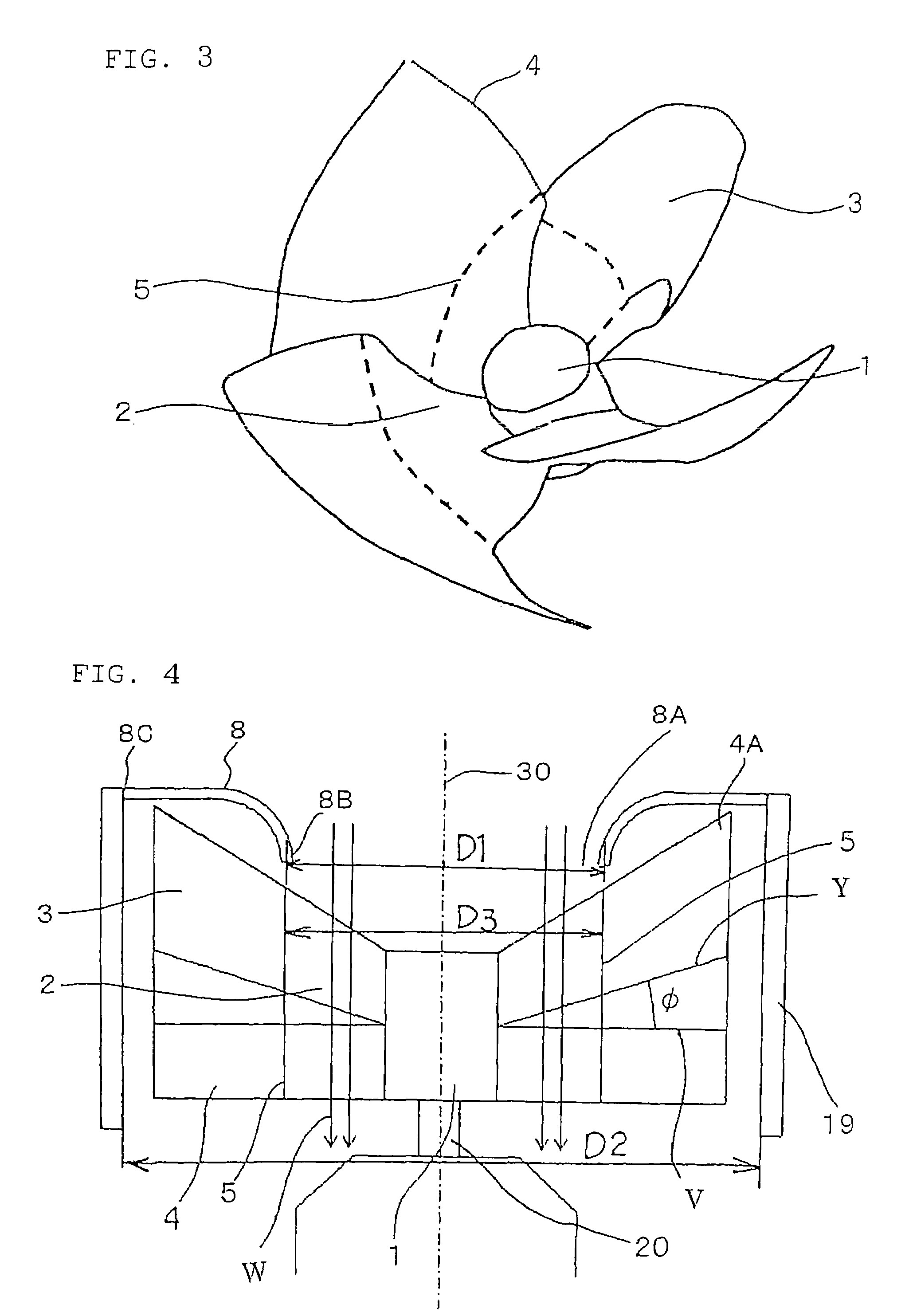
[0026]FIG. 1 is a front view of a blower according to Embodiment 1 of this invention as seen from the suction side thereof, FIG. 2 is a front view of the blower of FIG. 1 with a bell mouth 8 removed therefrom, FIG. 3 is a perspective view of blades 4 of the blower of FIG. 1, FIGS. 4 and 5 are sectional views taken along the line IV-IV of FIG. 1 when the blades 4 are rotating, and FIG. 6 is a sectional view taken along the line VI-VI of FIG. 5. FIG. 2 shows how the blades 4 are projected onto a plane perpendicular to a rotation axis 30 which is the center axis of a boss 1; it is a front view, as seen from the suction side, of a plane perpendicular to the rotation axis 30.

[0027]This blower is equipped with a motor shaft 20, a cylindrical boss 1 directly connected to the motor shaft 20 so as to be concentric therewith, four blades 4 mounted to the outer peripheral surface of the boss 1 circumferentially at equal intervals, a cylindrical case 19 surrounding the blades 4, and the bell mo...

embodiment 2

[0063]FIG. 9 is a diagram for illustrating the construction of a blower according to Embodiment 2 of this invention; it is a sectional view taken along the rotation axis (rotation center axis) 30 when the blades 4 are rotating.

[0064]In the above-described Embodiment 1, a case was shown in which the boundary portion 5 constituting the boundary between the sweepforward wing portion 2 and the sweepback wing portion 3 substantially coincides with the inner diameter of the bell mouth 8.

[0065]In contrast, in this embodiment, as shown in FIG. 9, the boundary portion 5 constituting the boundary between the sweepforward wing portion 2 and the sweepback wing portion 3 is situated on the outer peripheral side of the inner diameter of the bell mouth 8. That is, D1′3.

[0066]The blade profile of the blade 4 (impeller) on the inner peripheral side of the boundary portion 5 between the sweepforward wing portion 2 and the sweepback wing portion 3 is that of the sweepforward wing portion 2, and, in th...

embodiment 3

[0071]FIG. 10 is a diagram for illustrating the construction of a blower according to Embodiment 3 of this invention; it is a sectional view taken along the rotation axis 30 when the blades 4 are rotating.

[0072]As shown, for example, in FIGS. 2 and 3, in the above-described Embodiments 1 and 2, a composite blade is employed in which each blade 4 is equipped with the sweepforward wing portion 2 which is on the boss 1 side and which has a positive advance ratio value in the radial direction and the sweepback wing portion 3 which is on the outer peripheral side and which has a negative advance ratio value, with the arc length of each blade 4 gradually increasing from the boss 1 side toward the outer peripheral side. However, this invention is not restricted to the use of an impeller with such a composite blade; also in a blower equipped with an impeller (axial flow impeller) with an ordinary axial flow blade 40, a case 19 surrounding the impeller, and a bell mouth 8 cylindrically const...


PUM


Abstract

A blower includes: an impeller on which there are arranged axial flow blades 40 mounted at circumferential intervals to an outer peripheral surface of a boss; a case surrounding the impeller; and a bell mouth cylindrically constricted to guide gas into the case, wherein an inner diameter of the bell mouth is smaller than an outer diameter of the impeller. Further, each blade has, in the radial direction, a sweepforward wing portion situated on the boss side and exhibiting a positive advance ratio value, and a sweepback wing portion situated on the outer peripheral side of the blade and exhibiting a negative advance ratio value, with the arc length of each blade increasing from the boss side toward the outer peripheral side. Therefore, it is possible to achieve an improvement in ventilation efficiently, through an increase in static pressure and to achieve a reduction in noise.

Description

TECHNICAL FIELD[0001]This invention relates to a blower used, for example, for ventilation.BACKGROUND ART[0002]To achieve an improvement in efficiency in a blower, it is necessary to increase the static pressure, so that it is important that the flow in the centrifugal direction be increased in the relative flow field and that the velocity in the flow direction be reduced.[0003]Generally speaking, in a conventional blower, to increase the flow in the centrifugal direction, it is necessary to turn the flow behind the blades into a mixed flow. In view of this, for example, JP 53-116513 A discloses a construction in which the portion of the reference line of each blade from the root to the middle portion thereof is bent at a predetermined angle of inclination in the rotating direction, and the portion of the reference line from the middle portion to the tip end portion of the blade is bent at a predetermined angle of inclination in a direction opposite to the rotating direction so that...

Claims


Application Information

Patent Timeline
Patent Type & Authority Patents(United States)
IPC IPC(8): F04D29/54F04D17/06F04D29/38
CPCF04D17/06F04D29/384F04D29/386F04D29/4213
Inventor ARINAGA, MASAHIROKAGA, KUNIHIKOYAMADA, SHOJIOOTSUTA, KATSUHISAKIKUCHI, HITOSHIIWAMURA, YOSHIMIMAKINO, YASUYOSHI
Owner MITSUBISHI ELECTRIC CORP
Why Eureka
Try Eureka