Torque control system for all-wheel drive drivetrain

a technology of torque control system and all-wheel drive, which is applied in mechanical equipment, transportation and packaging, and gearing, etc., can solve the problems of disconcerting the operator, noise and vibration caused by the awd system being engaged, and the disadvantage of awd systems

Inactive Publication Date: 2008-02-19
DANA AUTOMOTIVE SYST GRP LLC
View PDF11 Cites 50 Cited by
  • Summary
  • Abstract
  • Description
  • Claims
  • Application Information

AI Technical Summary

Benefits of technology

[0010]The present invention provides an improved drivetrain of an all-wheel drive (AWD) motor vehicle allowing an infinitely variable torque distribution between drive axle assemblies of the motor vehicle.

Problems solved by technology

In tight cornering situations and during towing, these AWD systems present a disadvantage.
In cornering situations, noise and vibration can result from the AWD system being engaged.
While this is not detrimental to the powertrain during short durations, it can be disconcerting to the operator.
The AWD system is generally an on-road system and is not designed for off-road use.
Accordingly, in the front-weighted system, although the vehicle has good straight-ahead stability, it is inferior in steerability because of drifting out of a course.
However, the vehicle is liable to spin on a slippery road.
On the other hand, a disadvantage of the all-wheel drive vehicle is that all the four wheels may slip (slipping spin) at the same time, causing difficulty in driving.
However, in the conventional systems, the standard torque distribution ratio determined by the ratio of the pitch circles can not be changed, unless the diameters of differential gears change.
However, it is difficult to change the diameters because of a limitation of space.
In addition, if the vehicle is driven on a road surface having a low coefficient of friction under slipping conditions and the speed difference is small, the torque distribution can not be controlled.
Further, in the conventional systems for the fixed torque distribution control, the control range of the driving conditions is limited to a particular condition such as deceleration.
Thus, known drivetrains of the all-wheel drive motor vehicles, including but not limited to those discussed above, although proven to be acceptable for various vehicular driveline applications, are nevertheless susceptible to improvements that may enhance their performance and cost.

Method used


Image

  • Torque control system for all-wheel drive drivetrain
  • Torque control system for all-wheel drive drivetrain
  • Torque control system for all-wheel drive drivetrain

Examples


Embodiment Construction

[0017]The preferred embodiments of the present invention will now be described with the reference to accompanying drawings.

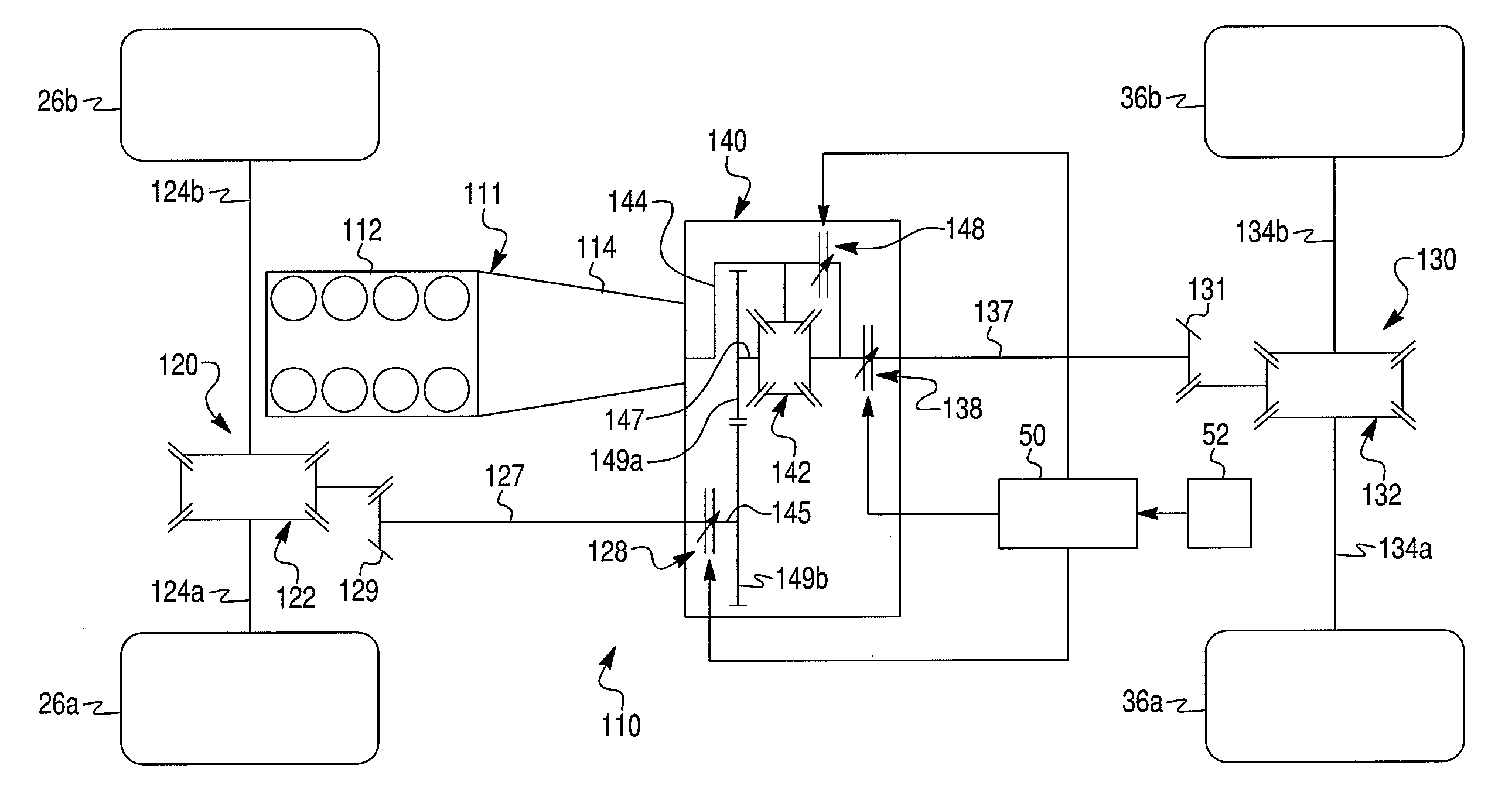
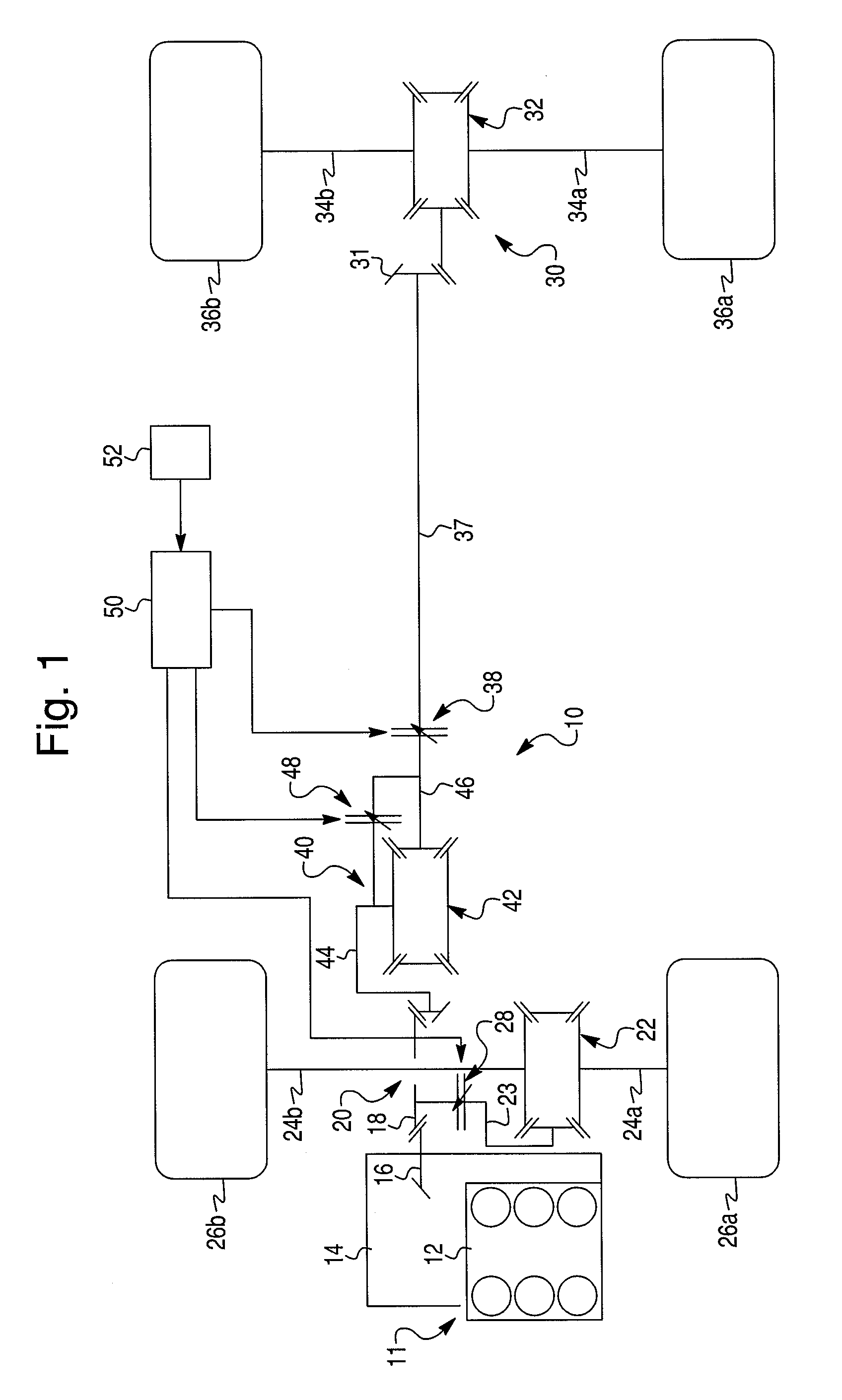
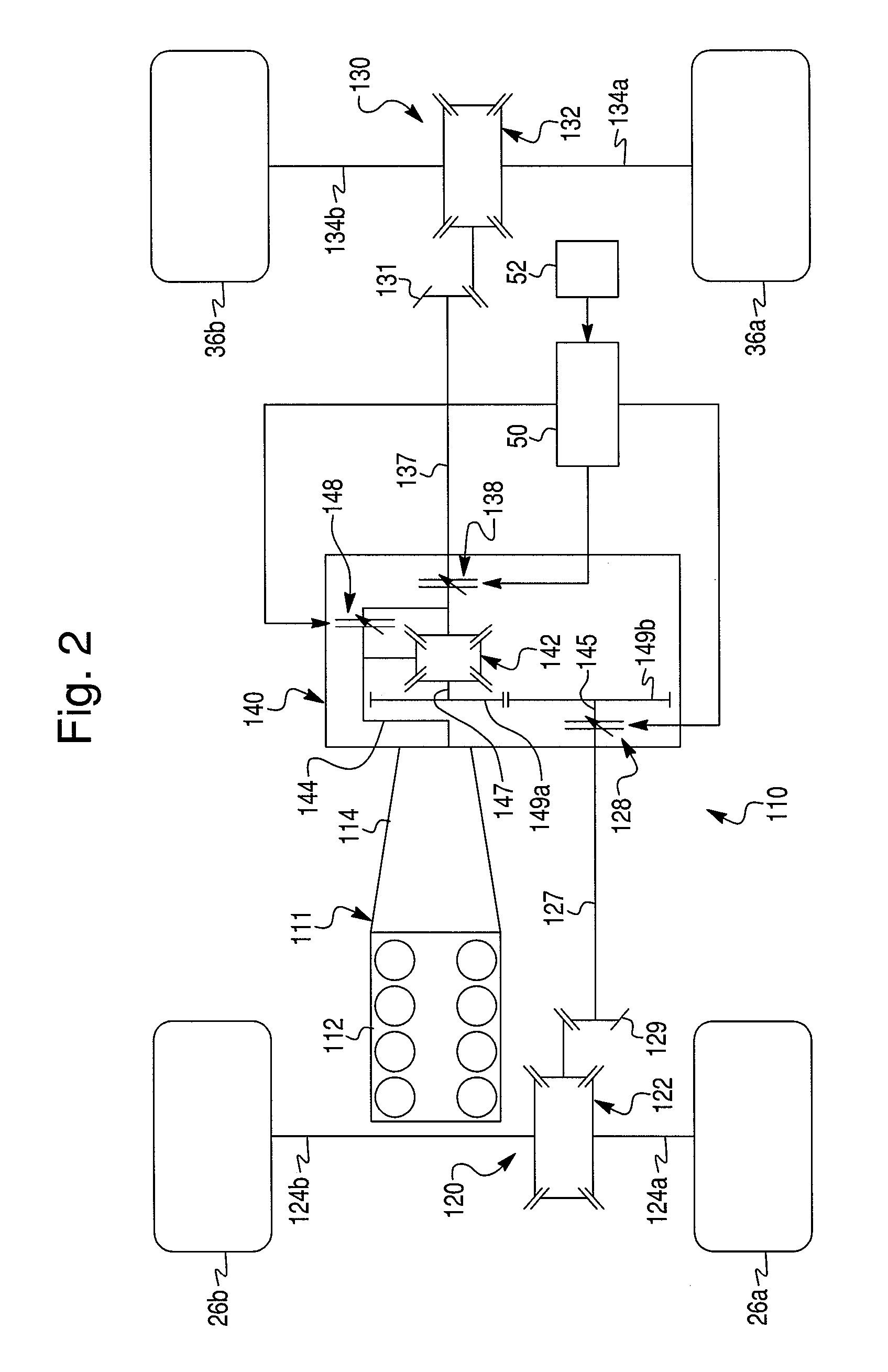
[0018]FIG. 1 schematically depicts a drivetrain 10 of an all-wheel drive (AWD) motor vehicle in accordance with the first exemplary embodiment of the present invention.

[0019]The AWD drivetrain 10 comprises a power drive unit 11, a selectively operable front drive axle assembly 20 selectively coupled to the power drive unit 11, a selectively operable rear drive axle assembly 30 and a power transfer unit 40 operably and selectively connecting the power drive unit 11 to the rear drive axle assembly 30. The power drive unit 11 includes an internal combustion engine (ICE) 12 mounted to a front end of the motor vehicle and coupled to an automatic or manual transmission 14. The power drive unit 11 is provided for selectively driving both or one of the front drive axle assembly 20 and the rear drive axle assembly 30.

[0020]The front drive axle assembly 20 includes a fron...


PUM


Abstract

A drivetrain of an all-wheel drive motor vehicle provided for selective actuation and control of the torque distribution between first and second drive axle assemblies to match various vehicle operating conditions. The drivetrain comprises a power drive unit including a prime mover, the first drive axle assembly driven by the power drive unit to drive a first set of wheels, the second drive axle assembly driven by the power drive unit to drive a second set of wheels, a first clutch unit provided to disconnect the first drive axle assembly from the power drive unit, and a second clutch unit provided to disconnect the second drive axle assembly from the power drive unit.

Description

BACKGROUND OF THE INVENTION[0001]1. Field of the Invention[0002]The present invention relates to torque control systems for motor vehicles in general, and more particularly to a torque control system for a drivetrain of all-wheel drive motor vehicles.[0003]2. Description of the Prior Art[0004]Many modern motor vehicles employ all-wheel drive (AWD) systems in which engine torque could be delivered to both front and rear wheels of the vehicle. These systems have been marketed in a number of forms, such as constant AWD systems, part-time AWD systems and on-demand AWD systems.[0005]Some AWD systems have a transfer case, which is controlled by the operator to select two wheel or four-wheel drive. If the operator selects the four-wheel drive condition, the vehicle drives all four wheels continuously. Some of these systems have employed overrunning clutches at two of the wheel to alleviate some of the disadvantages of AWD which result from tire pressure differential and cornering to name a...

Claims


Application Information

Patent Timeline
Patent Type & Authority Patents(United States)
IPC IPC(8): F16H48/02
CPCB60K17/346B60K17/35B60K23/0808
Inventor KROPPE, WILLIAM J
Owner DANA AUTOMOTIVE SYST GRP LLC
Why Eureka
Try Eureka