
Ceramic structure, method of manufacturing ceramic structure, and device for manufacturing ceramic structure

a ceramic structure and ceramic technology, applied in the direction of turning machines, turning machine accessories, drawing profiling tools, etc., can solve the problems of harmful to the environment and human body of particles in exhaust gas of internal combustion engines of vehicles, such as buses or tracks, construction machines or the lik

Active Publication Date: 2008-02-19
IBIDEN CO LTD
View PDF46 Cites 92 Cited by
  • Summary
  • Abstract
  • Description
  • Claims
  • Application Information

AI Technical Summary

Benefits of technology

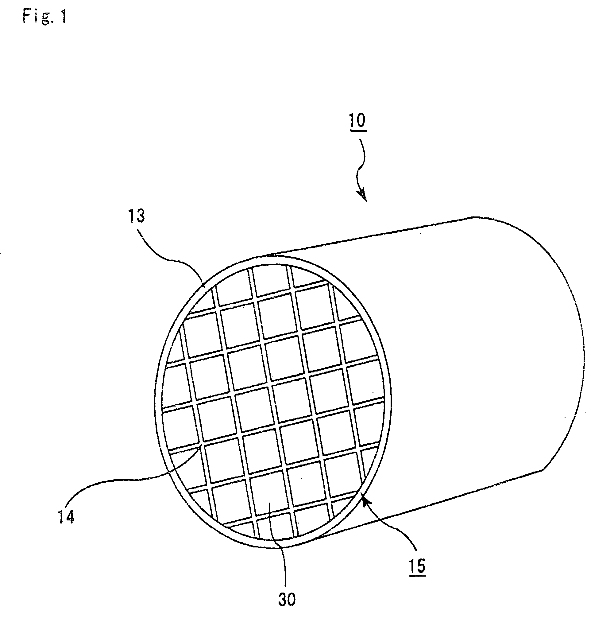
The present invention provides a ceramic structure that includes a plurality of porous ceramic members that are warped and connected at both ends with an adhesive. The ceramic structure can be produced by a process that includes providing the porous ceramic members with a space between them, supplying a bonding material to the space, and hardening the bonding material to bond the ceramic members to each other. The ceramic structure has improved strength and flexibility, and can be used in various applications such as filters, catalysts, and sensors.

Problems solved by technology

Particulates contained in an exhaust gas from an internal combustion engine of a vehicle, such as a bus or track, or a construction machine or the like are harmful to the environment and human bodies.

Method used


Image

  • Ceramic structure, method of manufacturing ceramic structure, and device for manufacturing ceramic structure
  • Ceramic structure, method of manufacturing ceramic structure, and device for manufacturing ceramic structure
  • Ceramic structure, method of manufacturing ceramic structure, and device for manufacturing ceramic structure

Examples


example 1

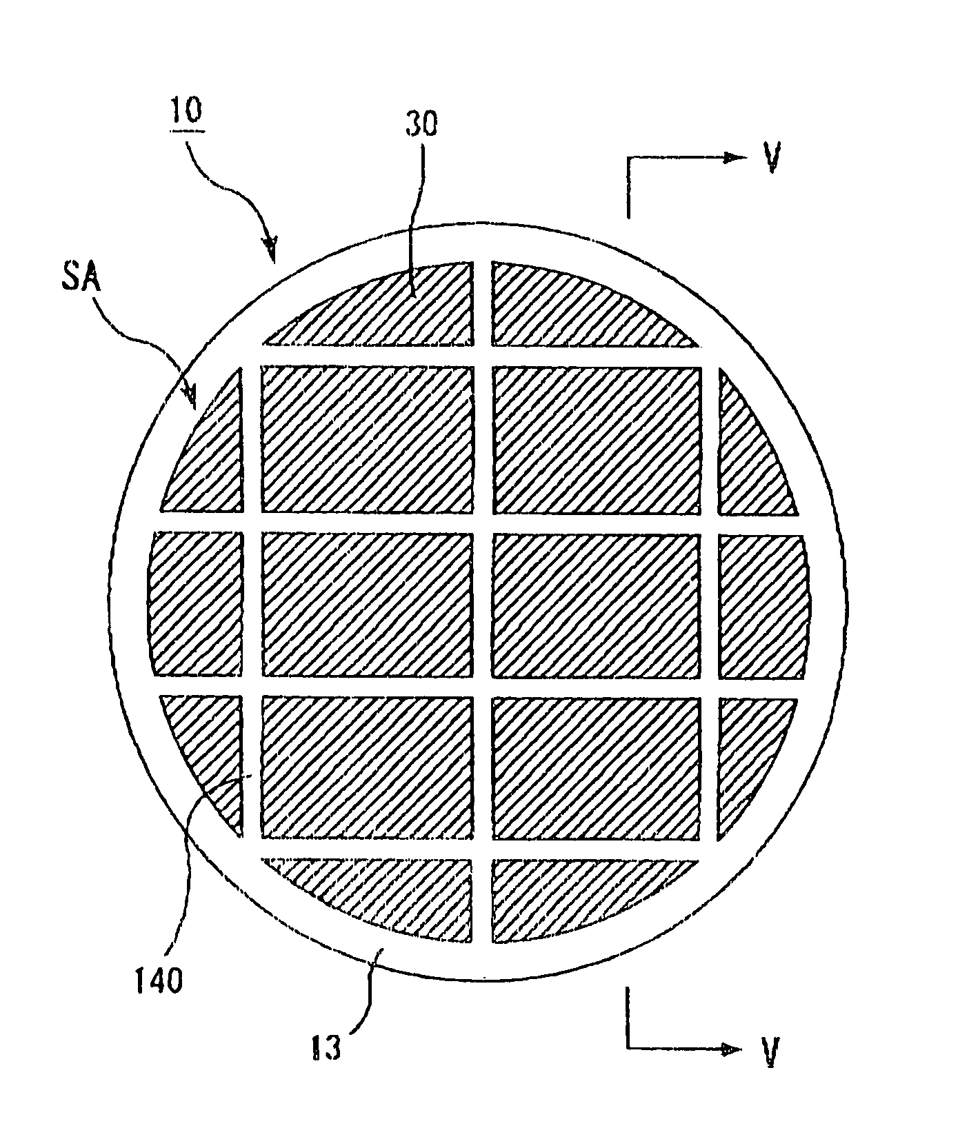
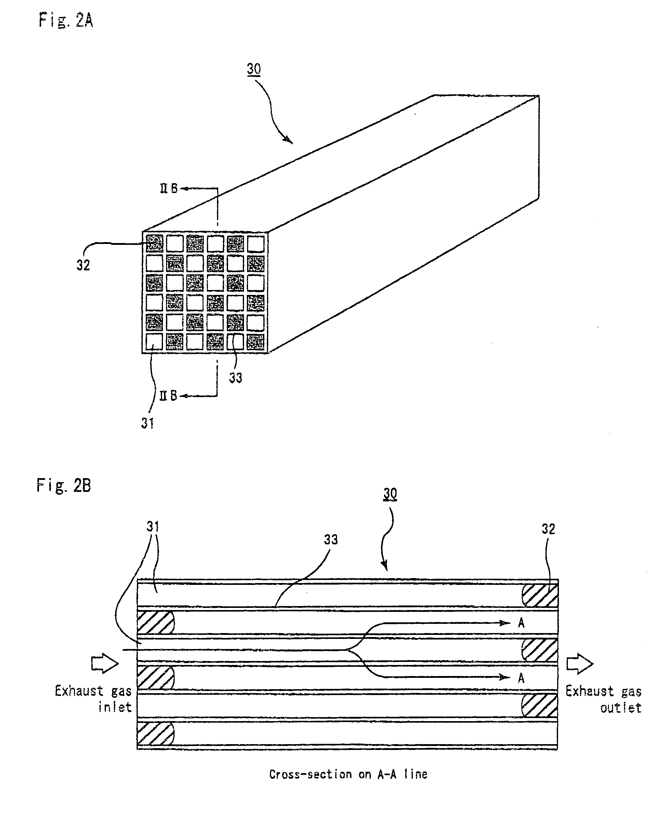
[0116](1) 70 wt % of α type silicon carbide powder with an average particle size of 10 μm, 30 wt % of β type silicon carbide powder with an average particle size of 0.7 μm, 5 wt % of methyl cellulose, 4 wt % of a dispersion agent, and 20 wt % of water were blended and evenly mixed to prepare a mixed composition as a source material. The mixed composition was filled in an extrusion molding machine and a ceramic compact with a honeycomb shape was prepared at the extrusion speed of 2 cm / min. The ceramic compact has a shape approximately similar to that of the porous ceramic member 30 shown in FIG. 3, and has a size of 33 mm×33 mm×254 mm, with the number of through holes being 31 / cm2 and the thickness of the partitions being 0.35 mm. In this example, the longitudinal length (254 mm) of the porous ceramic member 30 is obtained by measuring the distance between the end face SI on the inlet side and the end face SO on the outlet side and is represented in FIGS. 6A and 6B by the length of t...

examples 2 to 9 and reference examples 1 to 6

[0123]The ceramic structures 10 of porous silicon carbide were manufactured in the same way as done for Example 1, except for the changes in the amount of warping of the porous ceramic members 30 and in the length LM of the sealer-paste unfilled portion at either end portion of the ceramic member assembly 16 measured after press fitting the sealer paste 1400 as shown in Table 1.

[0124]The amount of warping of the porous ceramic members 30 was adjusted by changing the amount of warping of the degreasing / baking device. The length from the end face of the sealer-paste unfilled portion was adjusted by changing the amount of the sealer paste 1400 to be press-fitted.

examples 10 to 12 and reference examples 7 and 8

[0125]The ceramic structures 10 of porous silicon carbide were manufactured in the same way as done for Example 1, except that the amount of warping of the porous ceramic members 30 was changed, that the length from the end face of the sealer-paste unfilled portion at either end portion of the ceramic member assembly 16 after press fitting of the sealer paste 1400 was changed, and that the thickness of the spacers 142 made of a cardboard was changed to 2.0 mm, as shown in Table 1.

[0126]The amount of warping of the porous ceramic members 30 was adjusted by changing the amount of warping of the degreasing / baking device. The length from the end face of the sealer-paste unfilled portion was adjusted by changing the amount of the sealer paste 1400 to be press-fitted.


PUM

PropertyMeasurementUnit
longitudinal lengthaaaaaaaaaa
particle sizeaaaaaaaaaa

Abstract

A ceramic structure includes a plurality of porous ceramic members each being warped, each of the plurality of porous ceramic members having a bonding portion and end portions at both ends of each of the plurality of porous ceramic members in a longitudinal direction of each of the plurality of porous ceramic members, and an adhesive provided only on the bonding portion between the plurality of porous ceramic members to connect the plurality of porous ceramic members except for the end portions of the plurality of ceramic members.

Description

CROSS-REFERENCE TO RELATED APPLICATIONS[0001]The present application claims priority to Japanese Patent Application No. 2003-382820, filed Nov. 12, 2003. The contents of that application are incorporated herein by reference in their entirety.BACKGROUND OF THE INVENTION[0002]1. Field of the Invention[0003]The present invention relates to a ceramic structure, a method of manufacturing the ceramic structure, and a device for manufacturing the ceramic structure.[0004]2. Discussion of the Background[0005]Particulates contained in an exhaust gas from an internal combustion engine of a vehicle, such as a bus or track, or a construction machine or the like are harmful to the environment and human bodies. Thus, a ceramic structure serving as a ceramic filter is used to trap the particulates and clean up the exhaust gas.[0006]Japanese Patent Laid-Open Publication Nos. 2002-102627, 2002-224517 and 2002-219317 disclose a method of producing a ceramic filter as follows. First, porous ceramic mem...

Claims


Application Information

Patent Timeline
Patent Type & Authority Patents(United States)
IPC IPC(8): B01D46/00B29C65/70F01N3/022B01D39/20B01J35/04C04B35/565C04B35/63C04B35/80C04B37/00C04B38/00F01N3/28F01N13/18
CPCB01D39/2068C04B35/565C04B35/6316C04B35/806C04B37/005C04B38/008F01N3/0222F01N3/2828B01J35/04C04B35/00C04B38/0006Y10T428/24149B32B2315/02C04B2111/00793C04B2235/3418C04B2235/5228C04B2235/767C04B2235/80C04B2235/96C04B2237/083C04B2237/365F01N13/18F01N2260/10F01N2310/06F01N2330/06F01N2330/48F01N2450/28Y10S55/10Y10S55/30Y02T10/20Y10S55/05Y10S264/48Y02T10/12C04B35/80B01J35/56C04B37/003
Inventor ONO, MASAHARUTAKAHASHI, KOJIHOSHINO, TAKAFUMIKAWADA, HIDEYA
Owner IBIDEN CO LTD
Learn More