Discontinued cable shield system and method

a shielding system and cable technology, applied in the direction of insulated conductors, power cables, cables, etc., can solve the problems of insufficient, individual signals tend to increasingly interfere with each other, and disadvantages become more eviden

Active Publication Date: 2008-02-19
LEVITON MFG
View PDF14 Cites 89 Cited by
  • Summary
  • Abstract
  • Description
  • Claims
  • Application Information

AI Technical Summary

Problems solved by technology

Having many wire pairs in a cable can have advantages, such as increased data capacity, but as signal frequency used for the signals is increased to also increase data capacity, a disadvantage becomes more evident.
As signal frequency increases, the individual signals tend to increasingly interfere with one another due to crosstalk due to the close proximity of the wire pairs.
Twisting the two wires of each pair with each other helps considerably to reduce crosstalk, but is not sufficient as signal frequency increases.
Drawbacks from using additional physical spacing include increasing cable diameter and decreasing cable flexibility.
Connecting the conductive shield 16 to the connector shell can be problematic due to additional complexity of installation, added cable stiffness, special connectors required, and the necessity for an electrical ground available at both ends of the cable 10.
Furthermore, improper connection of the conductive shield 16 can reduce or eliminate the effectiveness of the conductive shield and also can raise safety issues due to improper grounding of the drain wire 18.
Unconnected ends of conventional shielding can give rise to undesired resonances related to the un-terminated shield length which enhances undesired external interference and crosstalk at those resonant frequencies
Although conventional approaches have been adequate for reducing crosstalk for signals having lower frequencies, unfortunately, crosstalk remains a problem for signals having higher frequencies.

Method used


Image

  • Discontinued cable shield system and method
  • Discontinued cable shield system and method
  • Discontinued cable shield system and method

Examples


Embodiment Construction

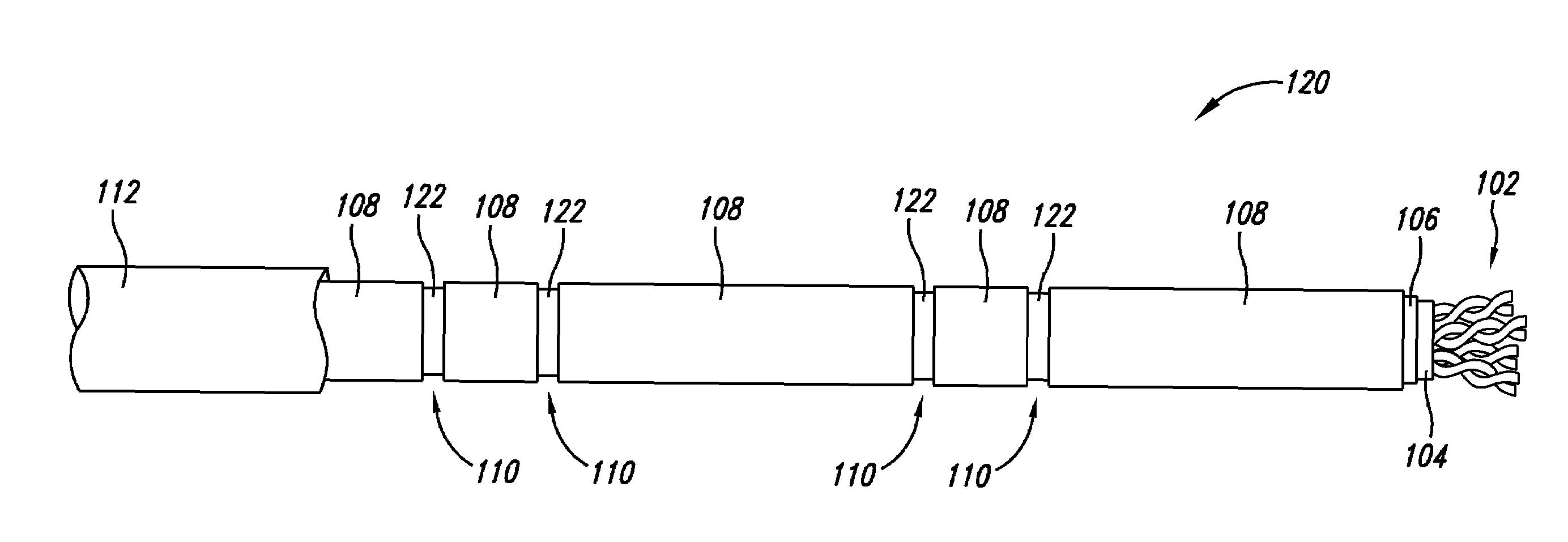
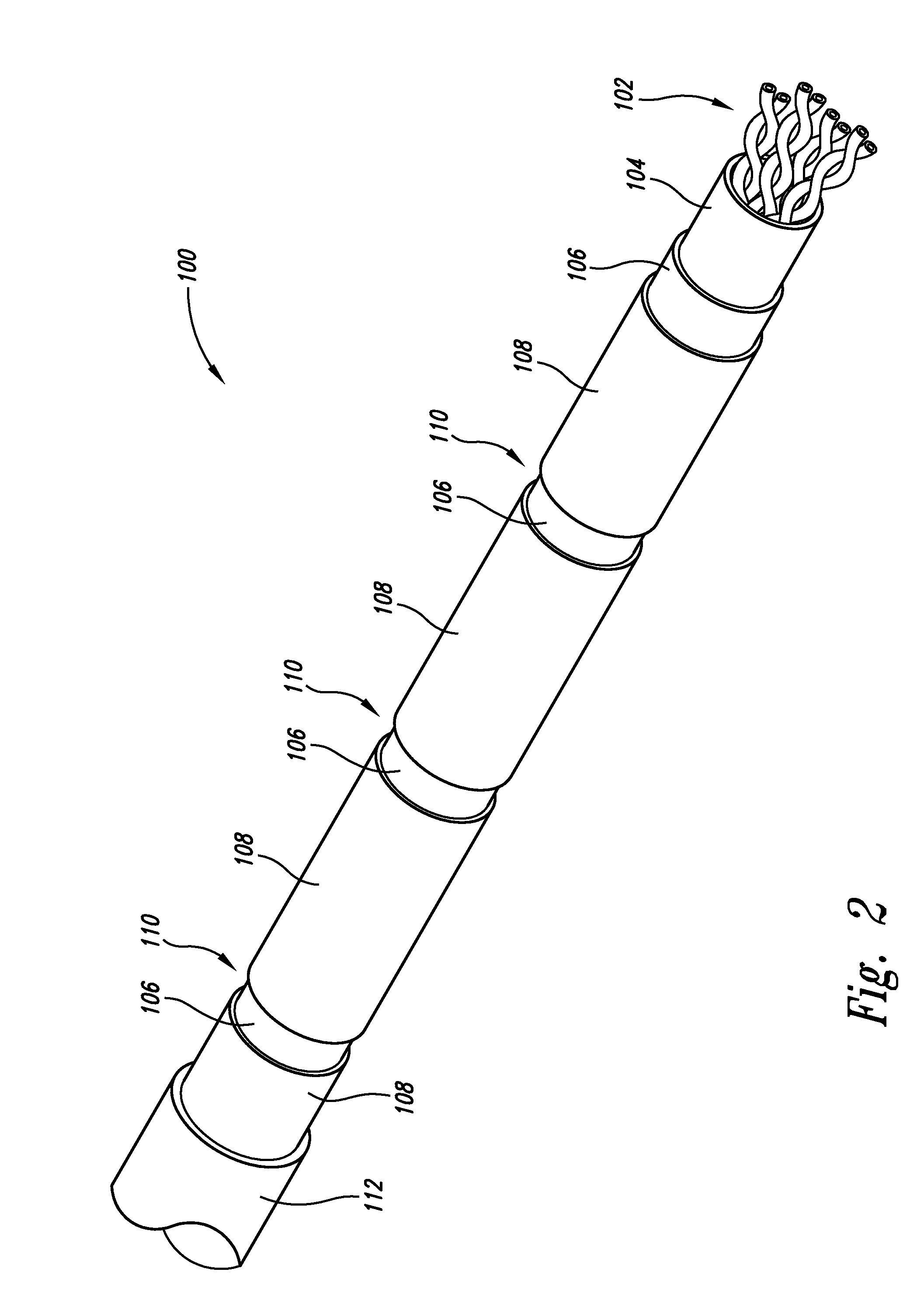
[0053]As discussed herein, implementations of a discontinuous cable shield system and method include a shield having a multitude of separated shield segments dispersed along a length of a cable to reduce crosstalk between signals being transmitted on twisted wire pairs of a cable. Implementations include a cable comprising a plurality of differential transmission lines extending along a longitudinal direction for a cable length, and a plurality of conductive shield segments, each shield segment extending longitudinally along a portion of the cable length, each shield segment being in electrical isolation from all other of the plurality of shield segments, and each shield segment at least partially extending about the plurality of the differential transmission lines.

[0054]A first implementation 100 of the discontinuous cable shield system is shown in FIG. 2, FIG. 3, and FIG. 4 as having a plurality of twisted wire pairs 102 contained by an inner cable sheath 104 and covered by insula...


PUM

PropertyMeasurementUnit
lengthaaaaaaaaaa
shapesaaaaaaaaaa
electrically conductiveaaaaaaaaaa

Abstract

Implementations of a discontinuous cable shield system and method include a shield having a multitude of separated shield segments dispersed along a length of a cable. The separated shield segments can serve as an incomplete, patch-worked, discontinuous, ‘granulated’ or otherwise perforated shield for differential transmission lines such as with twisted wire pairs.

Description

CROSS REFERENCE TO RELATED APPLICATION[0001]This application claims priority benefit of provisional application Ser. No. 60 / 665,969 filed Mar. 28, 2005.BACKGROUND OF THE INVENTION[0002]1. Field of the Invention[0003]The present invention is generally related to cable for transmitting signals, and more particularly related to reduction of crosstalk experienced between the signals.[0004]2. Description of the Related Art[0005]A metal based signal cable for transmitting information across computer networks, generally have a plurality of wire pairs (such as pairs of copper wires) so that a plurality of signals, each signal using a separate wire pair, can be transmitted over the cable at any given time. Having many wire pairs in a cable can have advantages, such as increased data capacity, but as signal frequency used for the signals is increased to also increase data capacity, a disadvantage becomes more evident. As signal frequency increases, the individual signals tend to increasingly ...

Claims


Application Information

Patent Timeline
Patent Type & Authority Patents(United States)
IPC IPC(8): H01B7/18
CPCH01B11/1008H01B11/06H01B11/08
Inventor SPARROWHAWK, BRYAN L.
Owner LEVITON MFG
Why Eureka
Try Eureka