Method and transducers for dynamic testing of structures and materials

a technology of dynamic testing and transducers, which is applied in the direction of instruments, specific gravity measurement, furnaces, etc., can solve the problems of affecting the accuracy of measurement, increasing the difficulty of measuring rotational impedance, and increasing the difficulty of overcoming problems

Inactive Publication Date: 2008-02-19
NANYANG TECH UNIV
View PDF6 Cites 5 Cited by
  • Summary
  • Abstract
  • Description
  • Claims
  • Application Information

AI Technical Summary

Problems solved by technology

The loading effects, calibration errors, and misalignments introduced by the three devices alone or together often affect the accuracy of measurement.
In cases where the object under testing is small in size, these problems are amplified, and more difficult to overcome.
Compared to translational impedance, measuring rotational impedance is more difficult, and more inaccurate.
Due to the lack of proper transducers for creating moments, and measuring rotational motion, only translational impedances are able to be identified in conventional dynamic testing.
This two-shaker approach possesses severe problems leading to large measurement errors.
The principal problem is the dependence of the measurement on the cross mobility at the receiver points 15.
When the connection point of the whole apparatus to the structure is not the symmetric centre, the cross mobility of the structure would cause errors as the exerted moment may generate linear forces or a moment along other axes which do not contribute to rotational velocity under measurement.
The two-shaker approach is further troubled by its very limited frequency range of excitation.
Tiny differences in specifications or performance could cause major errors as the measurements are based on the differences between the outputs of the two sensors.
Lastly, the size and complexity of the apparatus make its use and installation inconvenient and difficult.

Method used


Image

  • Method and transducers for dynamic testing of structures and materials
  • Method and transducers for dynamic testing of structures and materials
  • Method and transducers for dynamic testing of structures and materials

Examples


Embodiment Construction

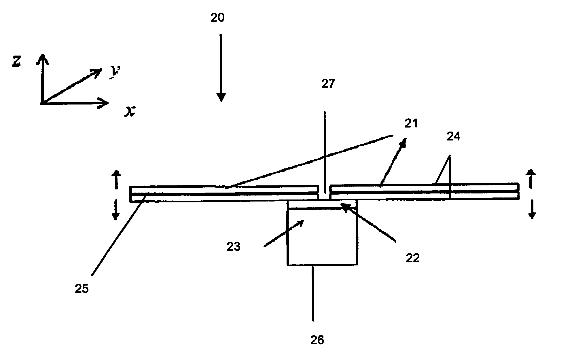
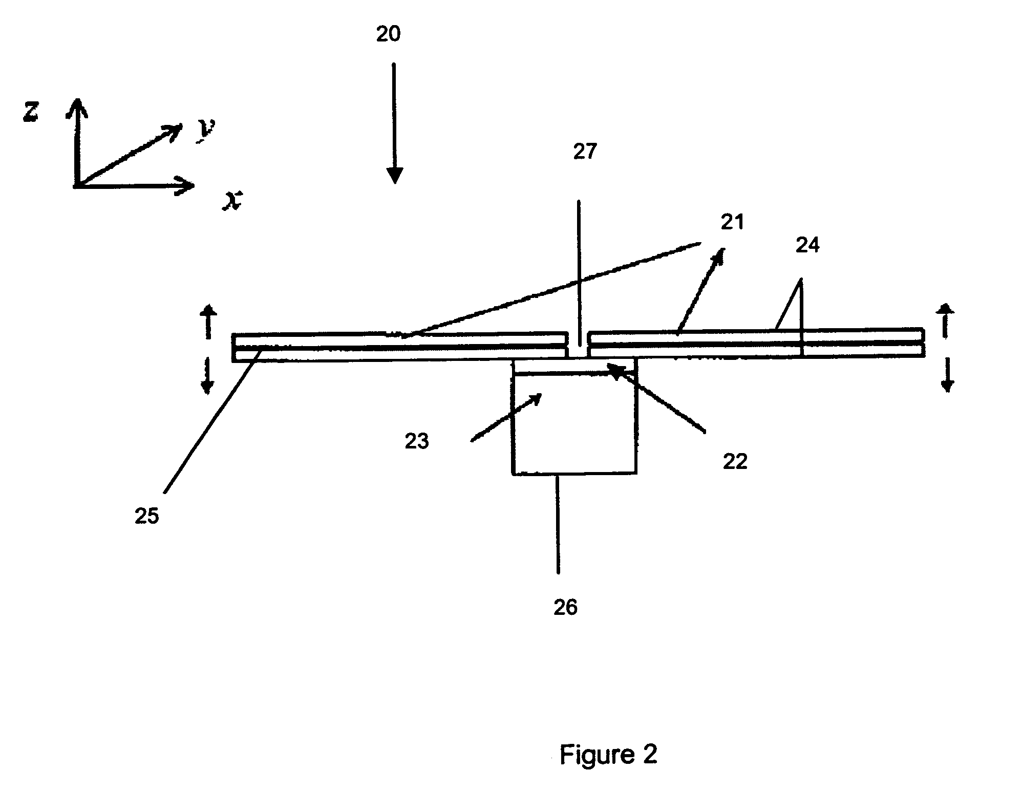
[0040]The schematic illustration of FIG. 2 shows transducer 20 comprising a pair of identical or substantially identical piezoceramic (PZT) bimorphs 21, an insulating layer 22, and a supporting block 23. The two bimorphs 21 have the same or substantially the same material characteristics and substantially the same dimensions, and are each attached to the insulating layer 22 at their inner ends. The insulating layer 22 electrically insulates the bimorphs 21, as does the gap 27 between their inner ends. It is preferred for the insulating layer 22 to be solid so as to not interfere with the transmission of forces and motion to block 23 and thus the specimen.

[0041]Each bimorph 21 consists of two piezoelectric elements 24, which are electrically connected in series and have opposite polarization directions. The bimorphs 21 are securely and rigidly attached to the supporting block 23 at their inner ends. A center metal shim 25 is inserted between the two piezoelectric layers 22 to improve...


PUM


Abstract

A transducer for dynamic testing of specimen is disclosed. The transducer comprises at least two equally-spaced actuators, and a supporting block for supporting the at least two equally-spaced actuators and for mounting the transducer to the specimen. Each of the at least two equally-spaced actuators is an electrically powerable for providing to the specimen: a force or a moment. The actuators may be bimorphs and the transducer may be able to operate as an actuator, a sensor, and simultaneously as an actuator and a sensor. This may be for the transducer being able to operate as a sensor, for measurement of at least one selected from the group consisting of: an excitation force exerted on the specimen, an excitation moment exerts on the specimen, a resultant translational velocity of the specimen at an excitation point, and a rotational velocity of the specimen at the excitation point. The at least two equally-spaced actuators are able to produce a force on the specimen when electricity supplied to the at least two equally-spaced actuators is in phase, and a moment on the specimen when the electricity supplied to the at least two equally-spaced actuators is out of phase.

Description

FIELD OF THE INVENTION[0001]This invention relates a method and transducers for dynamic testing of structures and materials and more particularly, through not exclusively, to a method and transducers for translational or rotational dynamic testing by one or more of: generating pure force or moment, detecting point translational or rotational impedance of structures, measuring force or moment, sensing linear or rotational velocity, and characterizing materials with dynamic behavior.BACKGROUND OF THE INVENTION[0002]Mechanical impedance of a structure or material, in general, is defined as the quotient of the excitation force or moment, and the caused velocity response along the same axis of excitation. If the excitation and motion are at the same point, it is a point impedance. If not, it is transfer impedance. If displacement or acceleration is used instead of velocity, the quotient is the dynamic stiffness, or inertiance, respectively. These quotients are often termed as Frequency R...

Claims


Application Information

Patent Timeline
Patent Type & Authority Patents(United States)
IPC IPC(8): H01L41/08
CPCG01M7/06H01L41/08H10N30/00
Inventor LING, SHIH FUHOU, XIAOYAN
Owner NANYANG TECH UNIV
Why Eureka
Try Eureka