Upper layer node, lower layer node, and node control method

a node control and upper layer technology, applied in data switching networks, frequency-division multiplexes, instruments, etc., can solve the problems of increasing the processing load, affecting the efficiency of network resources, so as to achieve the effect of effective exploitation of network resources

Inactive Publication Date: 2008-02-19
NIPPON TELEGRAPH & TELEPHONE CORP
View PDF25 Cites 7 Cited by
  • Summary
  • Abstract
  • Description
  • Claims
  • Application Information

AI Technical Summary

Benefits of technology

[0013]The present invention has been conceived of in order to resolve the above described type of problem, and its objective is to propose an upper layer node, a network, a program, and a recording medium, which can present a novel obstruction restoration control technique which is suitable for a multi-layer network, and with which effective exploitation of network resources can be anticipated.

Problems solved by technology

However, since it is not possible to recognize from the routers the fact that this type of obstruction restoration measure has been executed by the lower layer network, when an LSA packet arrives, updating of the topology which they themselves retain is quickly performed, and an alternate route is established.
In this manner, when a conventional obstruction restoration control technique is applied in its current form to a multi-layer network, the number of cases in which the routers perform updating of topology information and establish alternate routes which quickly become invalid increases, with the result that an increase of the processing load is entailed.
In particular, the processing load required for route calculation becomes great, and bad influences may be apprehended, such as deterioration of the processing speed for other processes which are performed between performing route calculations or the like, so that it is desirable to revise and improve this sort of mode of control in which this type of route calculation ends by being invalid.
In this manner, when a conventional obstruction restoration control technique is applied in its current form to a multi-layer network, the routers frequently rewrite the topology information to new topology information although after an extremely short time period it will be necessary to do so again, which is undesirable; and, furthermore, much undesirable new calculation of routing tables and establishment of alternate routes is performed.
As a result, not only is increased processing load imposed upon the routers although this load will shortly become invalid, but repercussions of confusion and congestion take place upon the network as a whole, since alternate routes which have been established are frequently returned back to the original routes after an extremely short time period, thus causing many attempts to be made again to occupy wavelengths which have just been released.

Method used


Image

  • Upper layer node, lower layer node, and node control method
  • Upper layer node, lower layer node, and node control method
  • Upper layer node, lower layer node, and node control method

Examples


Embodiment Construction

[0324]First, the first through the sixteenth preferred embodiments of the present invention will be explained.

The First Preferred Embodiment

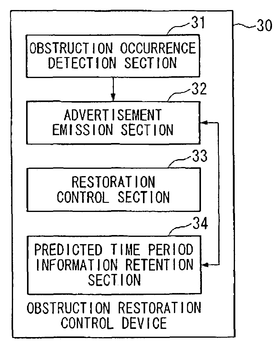
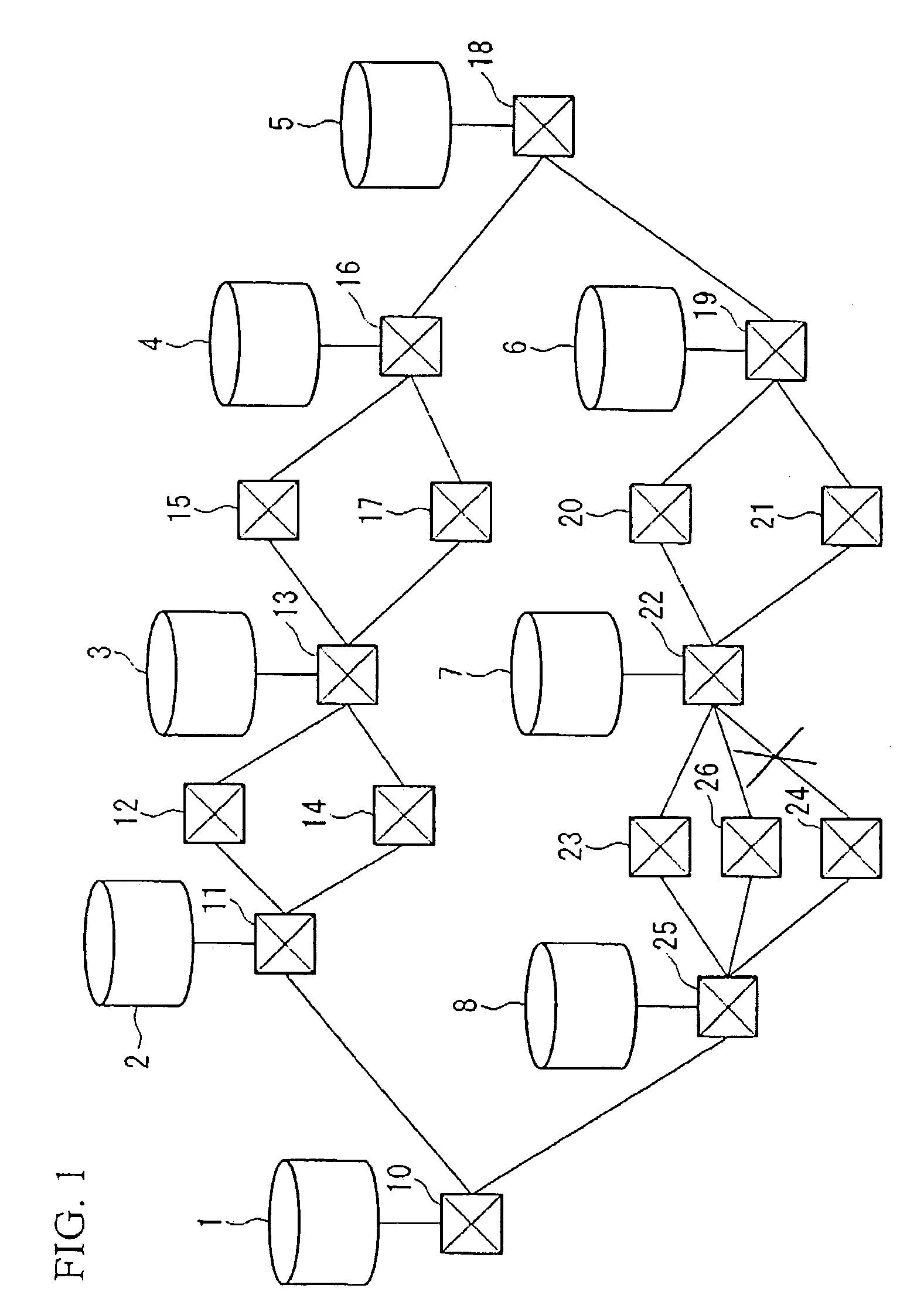
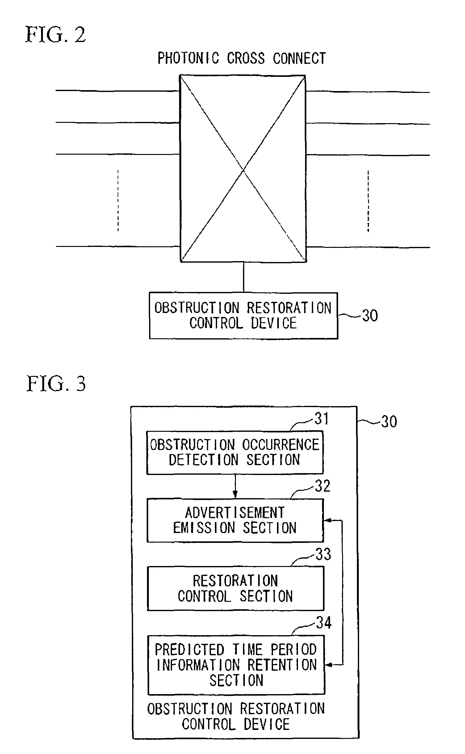
[0325]The first preferred embodiment of the present invention will be explained with reference to FIG. 1 through FIG. 4. FIG. 1 is a conceptual view of a network according to this preferred embodiment. FIG. 2 is a structural diagram of a photonic cross connect incorporated in this preferred embodiment. FIG. 3 is a block structural diagram of an obstruction restoration control device incorporated in this preferred embodiment. And FIG. 4 is a block structural diagram of a router of this preferred embodiment.

[0326]This first preferred embodiment is a network, comprising a plurality of nodes and transmission lines provided between these nodes; among this plurality of nodes, routers 1 through 8 are upper layer nodes and photonic cross connects 10 through 26 are lower layer nodes; at least two of these routers 1 through 8 are connected together by a l...


PUM


Abstract

An upper layer node is used in a multi-layer network which includes an upper layer network which performs switching and transfer in units of packets, and a lower layer network which includes optical transmission lines and optical switches and accommodate the upper layer network; this upper layer node being connected to the lower layer network which includes lower layer nodes including obstruction restoration sections, and transmission lines, and including: a section which detects the occurrence of an obstruction upon a transmission line which it accommodates; a section which advertises the detection result as obstruction information; a section which retains the topology information for the network; a section which updates the retained topology information according to advertised obstruction information, or obstruction information which it has detected; and an advertisement transfer section which advertises to other upper layer nodes the advertised obstruction information.

Description

BACKGROUND OF THE INVENTION[0001]1. Field of the Invention[0002]The present invention relates to a multi-layer network which is controlled in a unified manner by photonic cross connects, routers, SDH (Synchronous Digital Hierarchy) devices or the like. In particular, the present invention relates to GMPLS (Generalized Multi Protocol Label Switching).[0003]The present application is based upon patent applications Nos. 2002-060435, 2002-060449, 2002-060473, 2002-060477, 2002-060510, 2002-060513, and 2002-060525 filed in Japan, the contents of which are hereby incorporated herein by reference.[0004]2. Description of the Related Art[0005]In recent years, multi-layer networks which have become prevalent can control the photonic cross connects, routers, SDI devices and the like utilized therein in a unified manner. An example of this kind of multi-layer network is shown in FIG. 27. In the example of FIG. 27, a lower layer network consisting of a plurality of photonic cross connects 60 thr...

Claims


Application Information

Patent Timeline
Patent Type & Authority Patents(United States)
IPC IPC(8): H04J1/16H04Q11/00H04L69/40
CPCH04Q11/0062H04Q2011/0081H04Q2011/0088H04Q2011/009H04J14/0283H04J14/0284H04J14/0287H04Q2011/0077
Inventor YAMANAKA, NAOAKIOKI, EIJISHIOMOTO, KOHEIOKAMOTO, SATORUIMAJUKU, WATARU
Owner NIPPON TELEGRAPH & TELEPHONE CORP
Why Eureka
Try Eureka