
Adaptive beacon interval in WLAN

a beacon interval and adaptive technology, applied in the field of adaptive beacon intervals in wlans, can solve the problems of terminal generation traffic, consuming battery power, reducing throughput, etc., and achieve the effect of improving the overall combined performan

Inactive Publication Date: 2008-02-19
NOKIA CORP
View PDF3 Cites 84 Cited by
  • Summary
  • Abstract
  • Description
  • Claims
  • Application Information

AI Technical Summary

Benefits of technology

[0011]An object of the invention is to provide a beacon interval in a Wireless Local Area Network which improves the overall combined performance of the Wireless Local Area Network and its WLAN terminals.
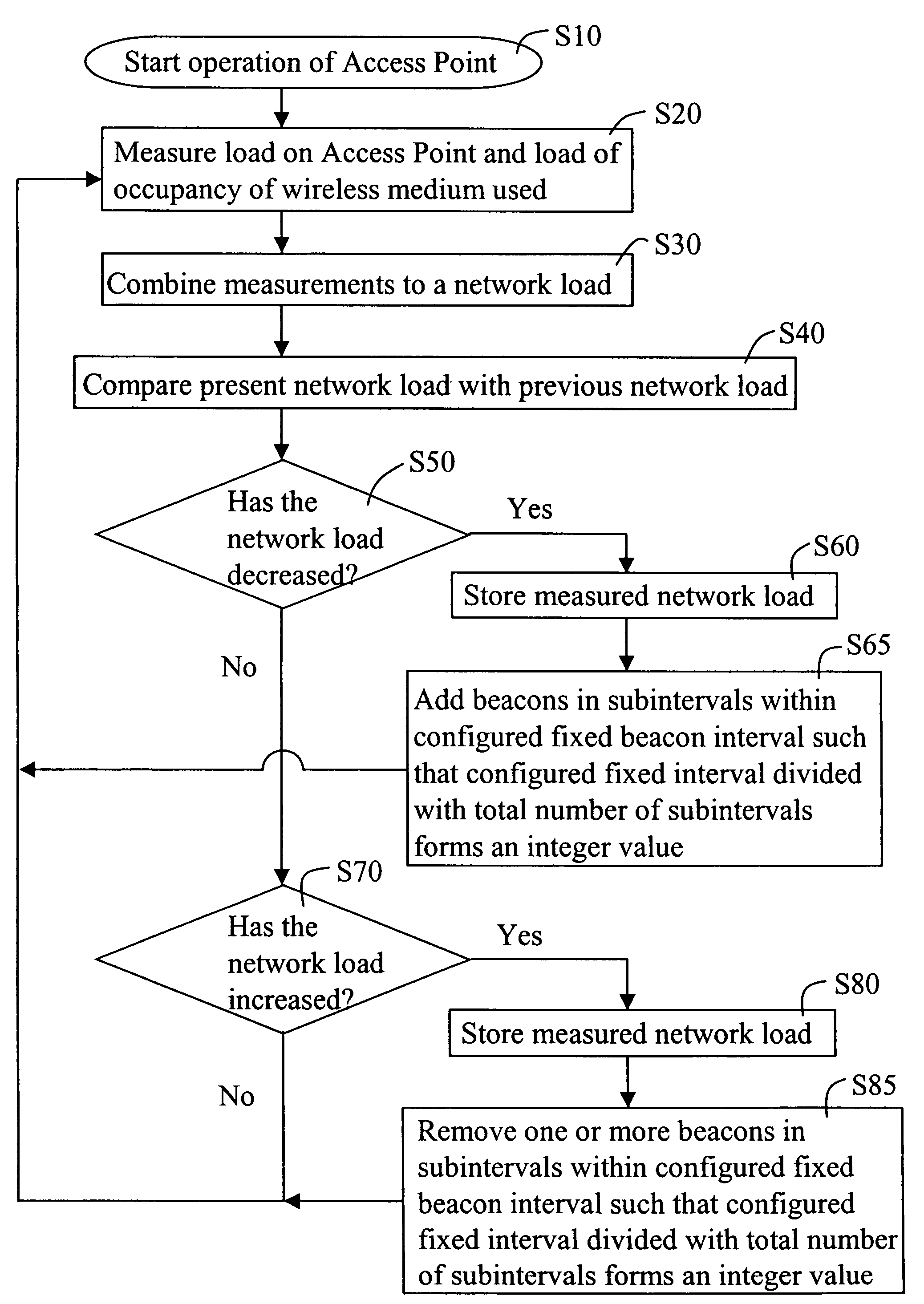
[0013]According to the present invention, the beacon frames in the Wireless Local Area Network are provided with an adaptive beacon interval. The interval is adapted in dependence on a current network load such that the length of the beacon interval is decreased when the network load is decreased and increased when network load is increased.
[0016]Thus, if the network load is high, the transmission frequency of the beacon frames is reduced, thereby increasing the beacon interval. This will increase the throughput in the Access Point and the capacity of the network. If the network load is low, the transmission frequency of the beacon frames is increased, thus decreasing the beacon interval. This will not negatively affect the throughput in the Access Point since the offered load does not fully load the network. Hence, an adaptive beacon interval as a function of network load minimizes the loss of overall network capacity, while enabling fact passive scanning and RSST updates by the terminals when the network is in a low load situation.
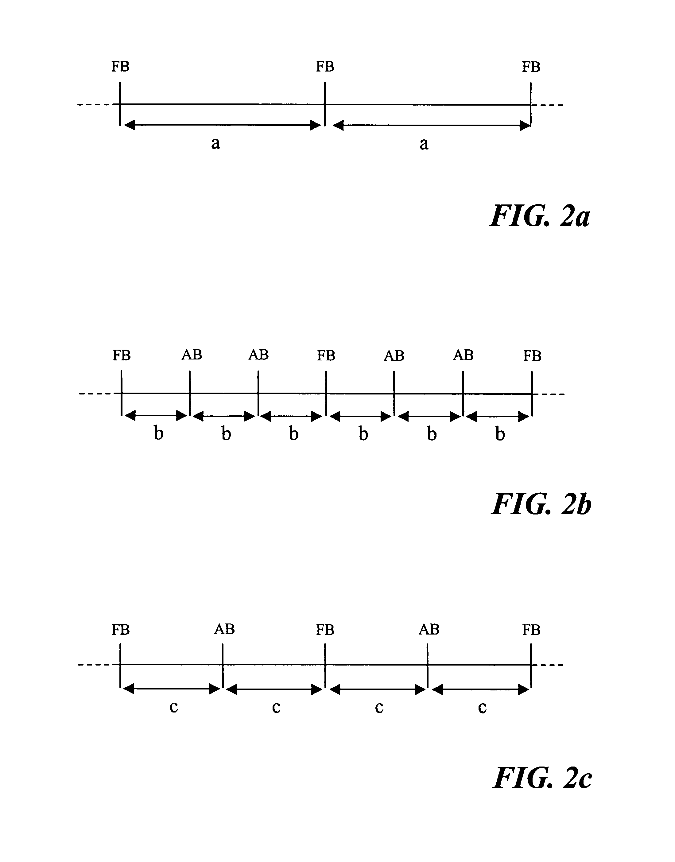
[0018]According to an embodiment additional beacon frames are transmitted between the fixed beacon intervals with which a network was configured before it was put in operation. By varying the number of additional beacon frames between the intervals, the overall effect will be transmissions of beacon frames with an adaptive interval. The additional beacon frames may be of a different frame type compared to the beacon frames defined by the existing standard.
[0019]Thus, this embodiment of the invention addresses the various existing 802.11 standards in which the beacon interval should be fixed. The embodiment modifies a network operating in accordance with these standards. The modified network will continue to transmit beacon frames at fixed intervals, thus meeting any standard with such requirement, while at the same time providing additional beacon frames between the fixed intervals. By varying the number of additional beacon frames between the fixed intervals, the combination of all beacon frames will result in a varying, adaptive beacon interval. This embodiment has the further advantage that it allows existing WLAN terminals to continue to operate in the network as if the network only provided the initially configured fixed beacon interval. Thus, there is no need to modify such terminals, while other WLAN terminals may be operated so as to benefit from the adaptive beacon interval provided by the network.

Problems solved by technology

In worst case, a WLAN terminal has to remain on a channel for the entire duration of a beacon interval, thereby consuming battery power and reducing throughput, in order to receive the beacon frame.
A drawback of active scanning is that WLAN terminal generates traffic by transmitting special requests to nearby Access Points.
If there are large number of active WLAN terminals with active scanning capability, the throughput available for useful user payload data is decreased.
However, it will the take a long time for WLAN terminals to scan for Access Points in the area and to update RSSI and load information for already found Access Points.
This obviously reduces terminal throughput and wastes battery.
Thus, there is a problem with that a particular fixed beacon interval in one situation will be regarded as too long, while the same beacon interval in another situation it will be too short.
As shown above, both of these situations will have a negative impact on the perceived overall performance.
Moreover, with dual band WLAN Access Points and dual band WLAN terminals this problem is even more severe since the amount of channels to scan through will be higher than in the case with only single band Access Points and single band terminals.

Method used


Image

  • Adaptive beacon interval in WLAN
  • Adaptive beacon interval in WLAN
  • Adaptive beacon interval in WLAN

Examples


Embodiment Construction

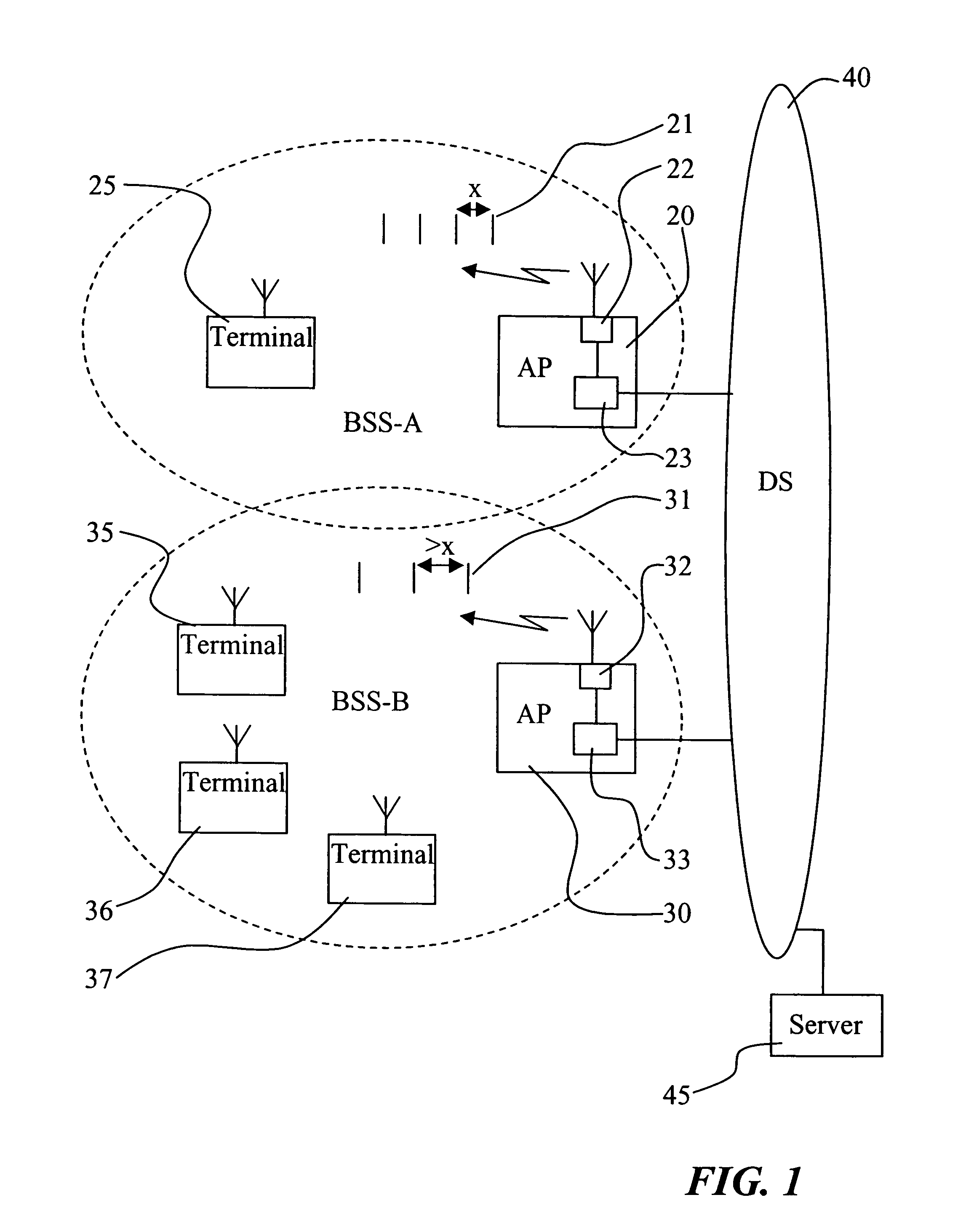
[0027]FIG. 1 shows an exemplifying Wireless Local Area Network(WLAN) having a structure and operation in accordance with the present invention.

[0028]The WLAN in FIG. 1 includes two so-called basic Service Sets, BSS-A and BSS-B, each including an Access Point (AP) and WLAN terminals in communication with or serviced by the Access Point. BSS-A includes the Access Point 20 and the WLAN terminal 25, while BSS-B includes the Access Point 30 and the WLAN terminals 35, 36 and 37. The Access Points 20, 30 are connected to a Distribution System(DS) 40 which typically is a wired Local Area Network or some other kind of backbone network interconnecting the different Access Points of the WLAN. The DS is typically further connected to one or more servers 45 and / or further networks, e.g. the Internet or the like (not shown). The DS allows a WLAN terminal to communicate, via an Access Point, with other terminals connected to the WLAN or with servers 45 or other entities to which connection can be ...


PUM


Abstract

The present invention relates to Wireless Local Area Networks and Access Points in such networks, in particular it relates to the control and use of varying beacon intervals in such networks. According to the present invention, the beacon frames in the Wireless Local Area Network are provided with an adaptive beacon interval. The interval is adapted in dependence on a current network load such that the length of the beacon interval is decreased when the network load is decreased and increased when network load is increased. The invention is applicable in existing as well as future IEEE 802.11 standards.

Description

TECHNICAL FIELD [0001]The present invention relates to Wireless Local Area Networks and Access Points in such networks, in particular it relates to the control and use of varying beacon intervals in such networks.BACKGROUND OF THE INVENTION [0002]Wireless Local Area Networks(WLAN) can be used to replace wired Local Area Networks or as extensions to wired LAN infrastructures and are standardized for example in accordance with the IEEE 802.11 standards.[0003]In a Wireless Local Area Network, beacon frames are used for enabling WLAN terminals to establish and maintain communications in an orderly fashion. The beacon frames are transmitted by the Access Points(AP) at regular intervals and include a frame header and a body with various information, i.a. a Service Set Identifier(SSID) identifying the name of a specific WLAN and a beacon interval specifying the time interval between two beacon transmissions. The beacon interval is a static, configurable parameter in an Access Point.[0004]O...

Claims


Application Information

Patent Timeline
IPC IPC(8): H04Q7/24H04L12/28H04W48/12
CPCH04W48/12
Inventor VAISANEN, ARIORAVA, PEKKAHAVERINEN, HENRY
Owner NOKIA CORP
Learn More