
Cooling system and method for using cooling system

a cooling system and cooling liquid technology, applied in the field of cooling systems, can solve the problems of high cost of cooling liquid, reduced cooling capacity or clogging, salt deposition, etc., and achieve the effect of less make-up water, less discharge costs, and reduced costs for using the cooling system

Inactive Publication Date: 2008-02-26
HOEK LOOS +2
View PDF19 Cites 5 Cited by
  • Summary
  • Abstract
  • Description
  • Claims
  • Application Information

AI Technical Summary

Benefits of technology

"The present invention provides a cooling system with improved efficiency and reduced water usage. The system includes a pellet reactor with a graft material for removing impurities from the cooling liquid. The graft material can be regenerated and the cooling liquid can be purified. The system also includes a supply for adding a CO32− providing compound to the cooling liquid to prevent the formation of Ca salts on the heat exchanging surfaces. The invention also provides a method for continuously or intermittently operating the cooling system. Overall, the invention provides a more efficient and cost-effective cooling system with reduced water usage and improved thermal efficiency."

Problems solved by technology

These known systems have the disadvantage, that deposition of salts, in particular calcium carbonate, is obtained on the heat exchanging surfaces at a relatively low concentration factor.
Increasing the concentration factor beyond the limits of the solubility product, will cause calcium salt deposition, especially on the high temperature surfaces of the process heat exchangers, causing reduced cooling capacity or clogging.
Because of the high costs of cooling liquid, the tendency in the industry is to discharge the cooling liquid continuously or periodically.
Therefore, there will be almost constantly a high concentration of impurities in the water and, consequently, the known cooling systems have to be operated at a lower concentration factor by an increased blow down.

Method used


Image

  • Cooling system and method for using cooling system
  • Cooling system and method for using cooling system
  • Cooling system and method for using cooling system

Examples


Embodiment Construction

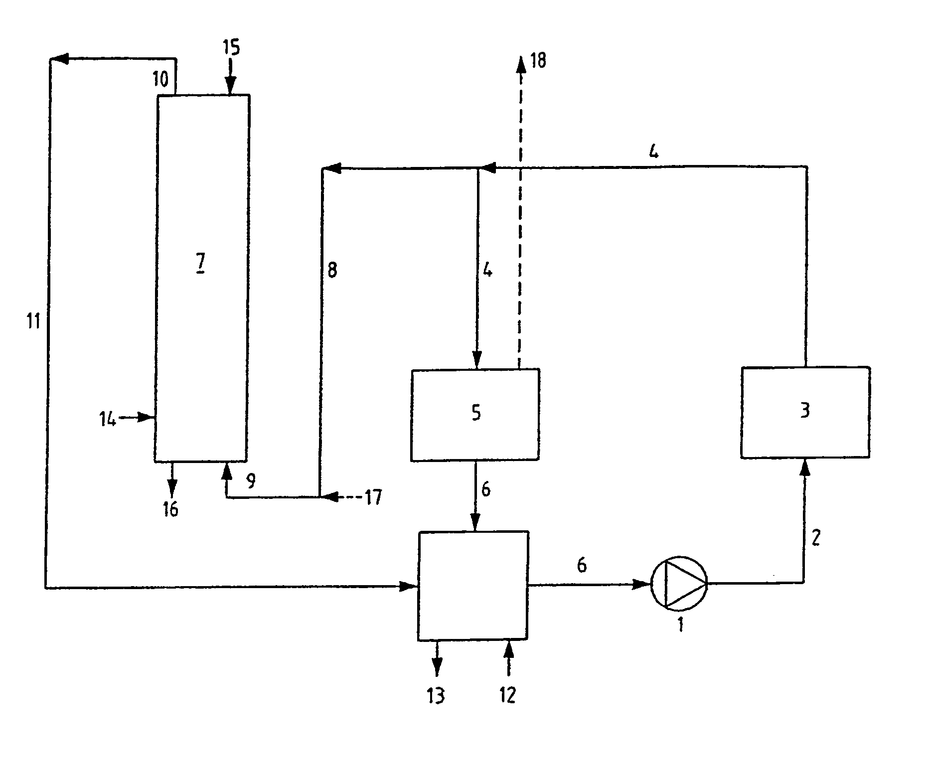
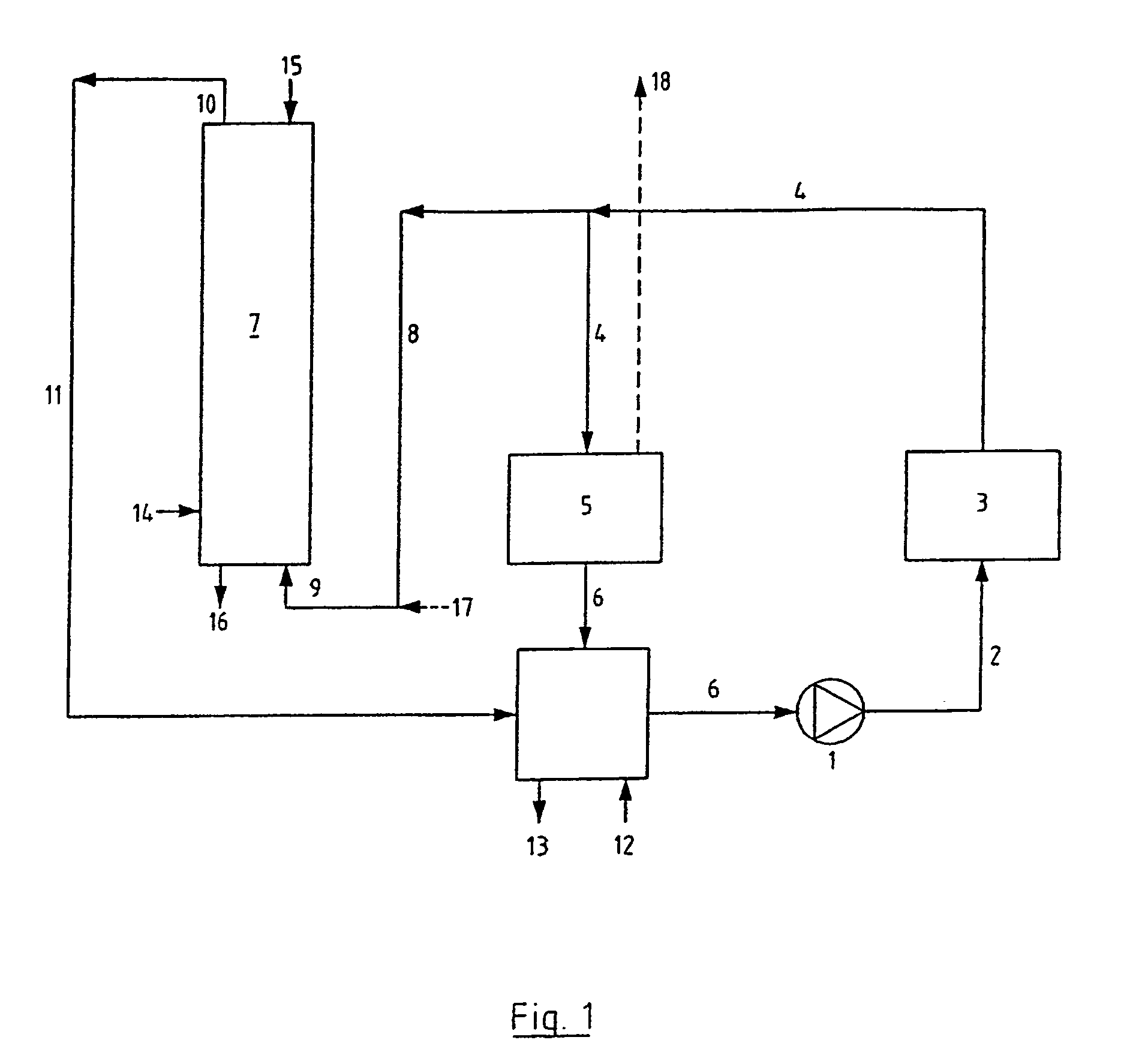
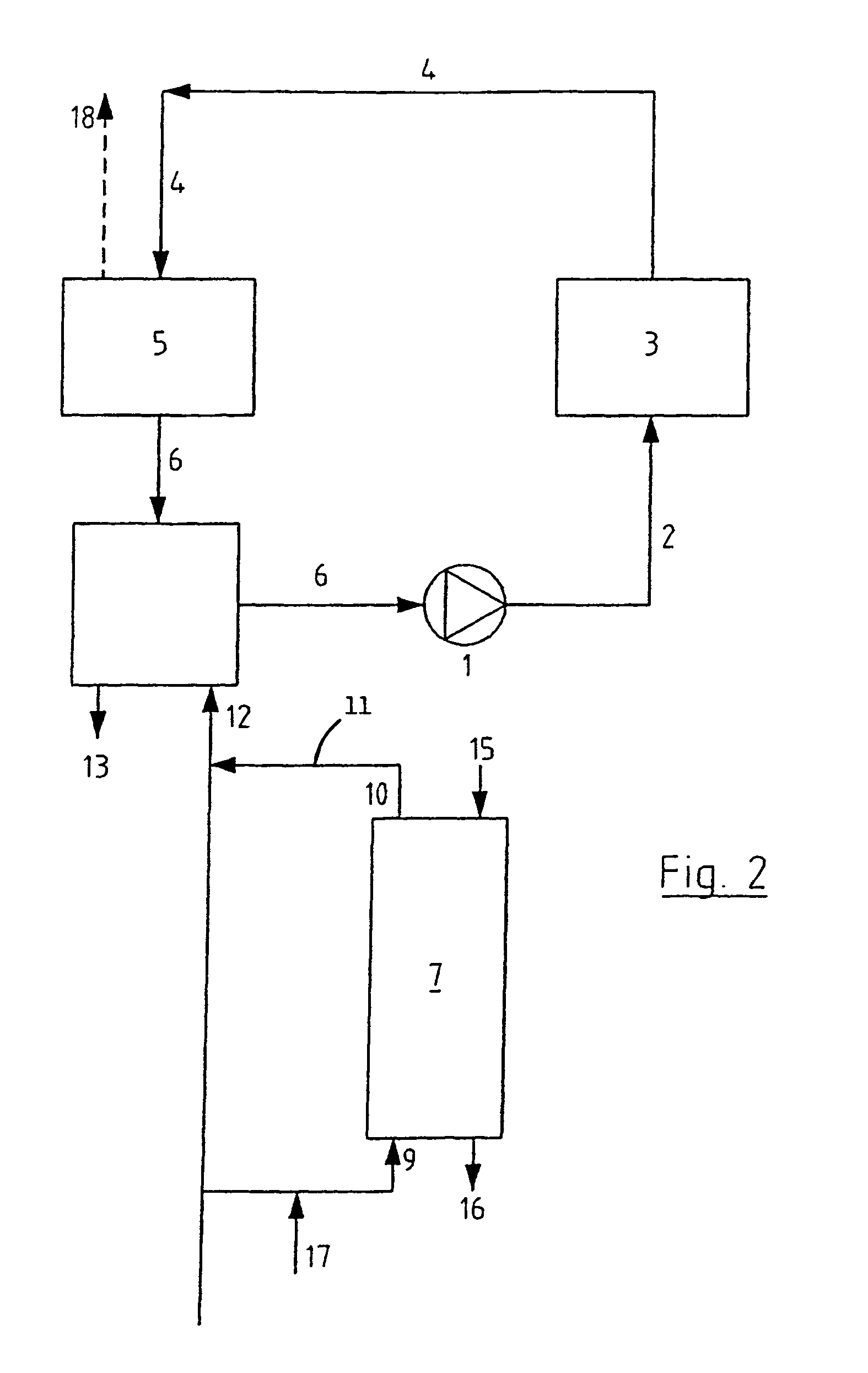
[0053]According to FIG. 1, cooling liquid is forced by a pump 1 through a pipe system 2 to a first heat exchanger 3 where cooling liquid is heated.

[0054]Subsequently, the heated cooling liquid is forced through a further pipe 4 to a second heat exchanger 5. The second heat exchanger 5 comprises an evaporator. The cooling liquid is cooled down in the second heat exchanger 5 by partially evaporating the cooling liquid. Loss of cooling liquid by evaporation, as indicated at 18, is made up by addition of fresh cooling liquid through make up 12. Subsequently, the cooled-down cooling liquid is returned to the pump 1 through pipes 6 and forced again to the first heat exchanger 3 through pipe system 2, where the cooling liquid is heated. A part of the cooling liquid through the pipe system 4 is branched off to a pellet reactor 7 through pipe system 8. The cooling liquid is supplied near the bottom 9 of the pellet reactor 7. Cooling liquid which has been treated in the pellet reactor 7 is re...


PUM

PropertyMeasurementUnit
concentrationaaaaaaaaaa
pHaaaaaaaaaa
concentrationaaaaaaaaaa

Abstract

A cooling system is provided having a first heat exchanger for heating a cooling liquid, a second heat exchanger, which preferably comprises an evaporator, for cooling the cooling liquid, and a pump for guiding the cooling liquid through the first and second heat exchanger. The system includes a pellet reactor through which cooling liquid is fed, so as to remove impurities from the cooling liquid by grafting the impurities onto graft material in the pellet reactor. A method is also provided for using such a cooling system. An advantage of the system is especially that calcium salts can be grafted onto the graft material, as a result of which the concentration factor of the cooling system can be increased significantly.

Description

CROSS-REFERENCE TO RELATED APPLICATIONS[0001]This application is a continuation of International Application No. PCT / NL2003 / 000651, filed Mar. 19, 2003, the disclosure of which is incorporated herein by reference.BACKGROUND OF THE INVENTION[0002]The present invention relates to a cooling system, having a first heat exchanger for heating a cooling liquid and a second heat exchanger for cooling the cooling liquid, a pump for guiding the cooling liquid through pipes and through the first and second heat exchanger, a drain for discharge of cooling liquid from the system and a supply for addition of fresh cooling liquid into the system. Preferably, the second heat exchanger comprises an evaporator. The invention also relates to a method for using such a cooling system.[0003]A cooling system and a method for using such a cooling system as mentioned above are known in the art. These known systems have the disadvantage, that deposition of salts, in particular calcium carbonate, is obtained ...

Claims


Application Information

Patent Timeline
Patent Type & Authority Patents(United States)
IPC IPC(8): F25D25/00F25B43/04C02F5/02F01P11/06F28D13/00
CPCC02F5/02F28D13/00C02F1/004C02F1/66C02F2103/023C02F2303/22
Inventor KRABBENDAM, PETER JOZEFVAN DER VEGT, ANDRIES PETERBLOMMAERT, MARCUS CLAUDIUS LEON FRANCIS
Owner HOEK LOOS
Learn More